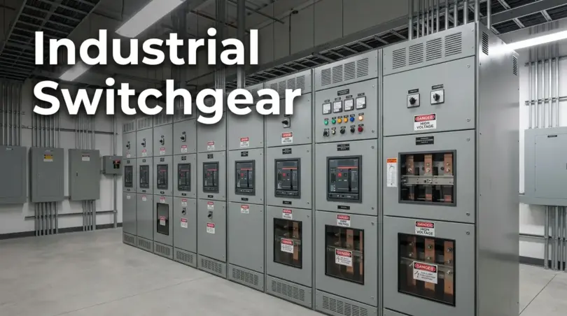

Industrial switchgear is a metal-enclosed assembly of circuit breakers, fuses, and switches used to control, isolate, and protect electrical distribution systems in factories, utilities, and commercial buildings. It detects abnormal conditions like short circuits or overloads and interrupts current before the fault can damage equipment or injure personnel. Medium voltage switchgear, rated roughly between 1 kV and 38 kV, is the type most commonly found in industrial power distribution.
What Is Industrial Switch Gear and What Does It Actually Do?
Industrial switchgear combines circuit breakers, disconnect switches, and fuses inside a shared metal enclosure to manage the flow of electricity through a facility. Its three core jobs are control (directing power to different areas), isolation (creating a safe zone for maintenance), and protection (clearing faults before they cause damage).
Those three functions sound simple written out like that, but each one matters for a different reason. Control keeps a facility flexible: you can shut down one production line for retooling without touching anything else. Isolation is what protects a technician who opens a compartment door; a properly isolated section has no live energy path back into it, which is the entire basis of lockout/tagout procedures. Protection is the part most people think of first, and it’s the reason switchgear exists at all. Left unchecked, a short circuit can release enough energy in a fraction of a second to melt copper busbars, vaporize insulation, and start a fire.
Switchgear shows up anywhere power needs to be distributed reliably and safely: manufacturing plants, utility substations, hospitals, data centers, and large commercial buildings. Standards for its design and testing come primarily from IEEE and ANSI in North America and IEC in most of the rest of the world, which is why you’ll see both sets of standard numbers referenced on spec sheets depending on the market.
How Industrial Switch Gear Works
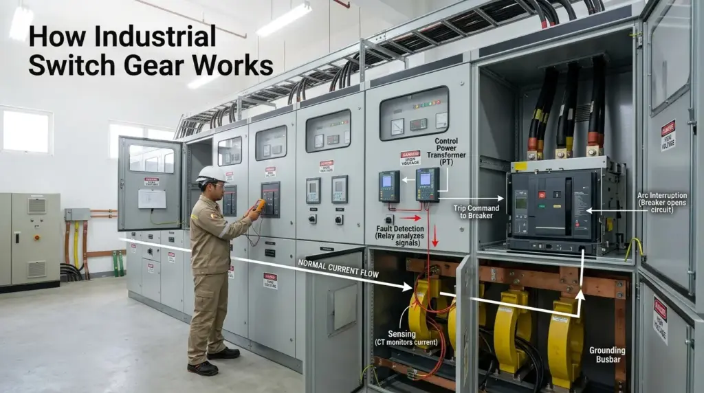
At a basic level, switchgear watches the system continuously and acts the moment something looks wrong. Instrument transformers step down the actual line current and voltage to levels a relay can safely measure, the relay compares those readings against preset thresholds, and if a fault is confirmed, it sends a trip signal to the breaker.
That process happens in stages, and it’s worth understanding each one, because most of the competitor content on this topic stops at “it detects a fault and trips a breaker,” which skips the part that actually determines how well protected a facility is.
Sensing. Current transformers (CTs) and potential transformers (PTs) continuously sample the current and voltage on each circuit. These aren’t optional extras; without accurate sensing, a protective relay has nothing reliable to act on.
Decision. A protective relay, whether an older electromechanical unit or a modern microprocessor-based device, compares the sensed values against programmed settings for overcurrent, ground fault, or undervoltage conditions. Modern relays also handle time-current coordination, meaning they’re set to trip in a specific sequence relative to other breakers upstream and downstream, so that only the smallest necessary section of the system goes dark.
Interruption. Once a trip signal fires, the breaker’s mechanism physically separates its contacts inside an interrupting medium (commonly vacuum in medium voltage gear today) fast enough to extinguish the resulting arc before it can sustain itself.
Isolation. The faulted section is separated from the rest of the system, which stays energized and operational. This selective response, rather than a blanket shutdown, is what separates well-designed switchgear from a system that just trips everything at once.
Switchgear vs. Switchboard vs. Panelboard: What’s the Actual Difference
These three terms get used loosely in the field, but they’re governed by different standards and built for different jobs. Switchgear is designed for higher fault-current environments and heavier compartmentalization than a switchboard or panelboard, and it’s tested to a different set of IEEE standards entirely.
| Equipment | Typical Standard | Voltage Range | Fault Current Handling | Common Use |
|---|---|---|---|---|
| Panelboard | UL 67 | Low voltage (under 600V) | Lower, branch-circuit level | Lighting, small loads, office buildings |
| Switchboard | UL 891 | Low voltage (under 600V) | Moderate | Building main distribution, smaller commercial loads |
| Switchgear | IEEE C37.20 series | Low, medium, and high voltage | Highest, engineered for utility and industrial fault levels | Plant main distribution, utility substations, large industrial loads |
The practical takeaway: if you’re specifying equipment for a facility’s main electrical service or anything feeding heavy industrial loads, you’re almost certainly looking at switchgear, not a switchboard. Getting this distinction wrong on a spec sheet can mean ordering equipment that isn’t rated for your actual fault current, which is a safety problem, not just a paperwork one.
Voltage Classes: Where Medium Voltage Switchgear Fits
Switchgear is generally grouped into low, medium, and high voltage categories, though the exact cutoffs vary slightly depending on which standard you’re reading. IEEE defines low voltage as up to 600V and medium voltage as roughly 600V to 69 kV, while many equipment manufacturers and IEC-based markets treat medium voltage more narrowly, as 1 kV to 38 kV.
This inconsistency trips up a fair number of people comparing specs across manufacturers or regions, so it’s worth calling out directly rather than glossing over it the way most switchgear overviews do.
- Low voltage (LV): Up to 600V by IEEE definition (the 2014 NEC extended some low-voltage classifications up to 1,000V). Used for lighting, HVAC, and smaller motor loads in commercial and light industrial settings.
- Medium voltage (MV): Roughly 1 kV to 38 kV in most practical industrial applications, though IEEE’s formal range extends to 69 kV. This is the workhorse range for utility distribution, large manufacturing campuses, hospitals, and data centers.
- High voltage (HV): Above 69 kV under IEEE, or above roughly 35-38 kV under some other conventions. Reserved for transmission networks and major substations.
A single medium voltage switchgear lineup is usually rated by its maximum voltage class rather than the exact operating voltage. For example, 15 kV-class switchgear is commonly applied at actual system voltages like 12.47 kV or 13.8 kV, not exactly 15 kV.
Types of Medium Voltage Switchgear
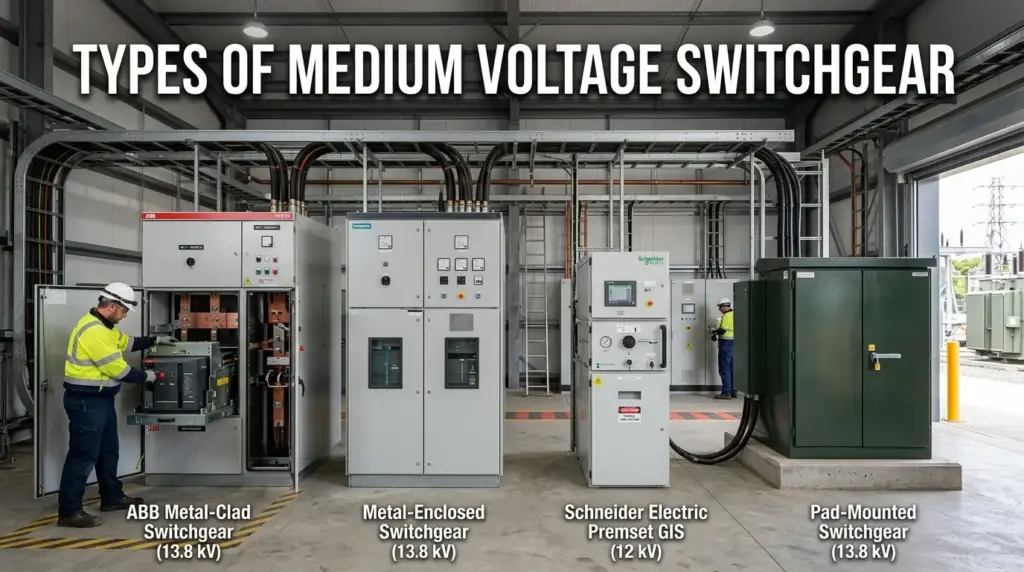
Once you’re in the medium voltage range, the equipment splits into several construction types, each suited to different space, safety, and maintenance requirements.
Metal-Clad Switchgear
Metal-clad switchgear encloses every major component, incoming bus, outgoing bus, instrumentation, and the main breaker, in separate metal compartments, and it’s built with a draw-out (removable) circuit breaker for easier maintenance. It’s defined by IEEE C37.20.2 and typically covers 5 kV to 38 kV. This is the type you’ll see most often in industrial facilities and power generation plants because the compartmentalization limits how far an internal fault can spread.
Metal-Enclosed Switchgear
Metal-enclosed switchgear (IEEE C37.20.3) houses breakers, fuses, and metering equipment in shared compartments without the same level of internal barriers as metal-clad gear. It costs less and takes up less engineering complexity, and it’s common in commercial and lighter industrial applications above 480/600V service.
Compact and Gas-Insulated Switchgear
Compact switchgear uses sealed circuit breakers and disconnects in a smaller footprint, built to IEEE C37.20.9 and IEC 62271. It’s the practical answer when floor space is tight or access is limited, which is increasingly common in retrofits and urban facilities where there simply isn’t room to expand.
Pad-Mounted and Vault Switchgear
Built to IEEE C37.74, these designs serve underground distribution systems in the 5-38 kV range. Pad-mounted gear sits above grade in a tamper-resistant enclosure; vault switchgear is designed to be operated from inside an underground vault, which matters for utility feeder work and dense urban distribution.
Switch Gear Insulation Mediums
The insulating medium is what keeps energized components from arcing to each other or to ground inside the enclosure, and the choice affects both equipment size and maintenance needs.
Air-insulated switchgear (AIS) uses ordinary air as the dielectric. It’s the least expensive option and mechanically the simplest, but air has relatively low dielectric strength, so AIS equipment needs to be physically larger to maintain safe clearances.
Gas-insulated switchgear (GIS) typically uses SF6 (sulfur hexafluoride) gas sealed inside a tank. SF6 has significantly higher dielectric strength than air, which lets manufacturers build far more compact equipment, and the sealed design largely eliminates routine contact maintenance. The tradeoff worth knowing: SF6 is a potent greenhouse gas, and some jurisdictions are moving toward tighter handling and disposal rules, which is pushing manufacturers to develop SF6-free alternatives using vacuum and solid-dielectric technology.
Fluid-insulated switchgear uses mineral oil or fire-resistant alternatives like ester-based fluids. Fluid adds a cooling benefit on top of insulation, though oil-filled equipment carries added fire and environmental spill considerations that AIS and vacuum designs avoid.
Vacuum interruption has become the standard interrupting technology inside modern medium voltage breakers regardless of the overall insulating medium, because vacuum bottles extinguish an arc quickly with minimal contact wear, extending maintenance intervals significantly compared to older air or oil break technology.
Key Components of an Industrial Switchgear Assembly
A working switchgear lineup depends on several components acting in coordination, not any single part in isolation.
- Circuit breakers interrupt fault current and can be closed and reopened repeatedly, unlike a fuse.
- Fuses melt at a set current/time threshold to clear a fault; often paired with a switch in medium voltage gear to combine overcurrent protection with manual switching.
- Disconnect switches provide a visible, physical break in the circuit for maintenance safety, separate from the breaker’s function of clearing faults under load.
- Busbars carry current between sections of the assembly and are braced to withstand the mechanical forces of a short circuit without deforming.
- Protective relays monitor current and voltage and issue trip commands; modern microprocessor relays also log event data useful for troubleshooting after a fault.
- Instrument transformers (CTs and PTs) scale down high current and voltage to levels relays and meters can safely read.
- Control panels give operators a central point to monitor status, issue commands, and view alarms, often integrated with SCADA systems in larger facilities.
Switchgear Design Considerations That Actually Matter
Specifying switchgear design correctly comes down to matching the equipment’s ratings and construction to real conditions on site, not just picking the highest numbers available. A few factors deserve more attention than they typically get.
Short-circuit withstand rating. This is the maximum fault current the switchgear’s bus structure can survive without damage, separate from the breaker’s interrupting rating. It needs to exceed the actual available fault current from the utility connection, which requires a fault current study, not an estimate.
Continuous current rating. The maximum current the main bus and overcurrent devices can carry indefinitely without tripping or overheating. Medium voltage switchgear commonly ranges from 600A to 4000A depending on facility load.
Environmental conditions. Ambient temperature, humidity, altitude, and airborne contamination all affect how equipment performs and how long it lasts. Equipment rated for a clean, climate-controlled electrical room will underperform in a hot, dusty industrial environment unless the enclosure and derating are matched to actual conditions.
Protective relay coordination. This is one of the most commonly skipped steps in smaller projects. Coordination studies set relay time-current curves so that the breaker closest to a fault trips first, rather than a fault upstream shutting down an entire facility. Without it, switchgear technically works, but it doesn’t work efficiently.
Physical access and clearance. Working clearances for switchgear are governed by NEC Article 110.26 in the U.S., and they’re not optional design flexibility; insufficient clearance is a common finding in electrical inspections and a real safety hazard during maintenance.
Scalability. Facilities grow. Leaving physical and electrical headroom in a switchgear lineup, extra breaker positions, spare bus capacity, avoids a full system replacement a few years down the line.
Arc-Resistant Switchgear and Arc-Flash Safety
Arc-resistant switchgear is built to contain and redirect the energy of an internal arc fault away from personnel, rather than simply containing normal operating conditions. It’s tested to IEEE/ANSI C37.20.7, which defines several classifications:
- Type 1: Arc resistant at the front of the equipment only.
- Type 2: Arc resistant around the entire perimeter.
- Type 2B: Arc resistant around the perimeter, even with control compartment doors open.
- Type 2C: Arc resistant between adjacent internal compartments as well as around the perimeter.
The stakes here are genuinely serious. An arc flash event can generate temperatures exceeding 35,000°F, roughly four times hotter than the surface of the sun, in the space of milliseconds. Conventional switchgear provides a reasonably safe environment under normal operation, but it isn’t built to withstand that kind of energy release. Arc-resistant construction, paired with proper arc-flash labeling and personal protective equipment, is what actually protects the people standing in front of the equipment.
How to Choose Industrial Switchgear for a Facility
Selecting switchgear is less about comparing spec sheets side by side and more about working backward from your facility’s actual electrical conditions.
- Run a fault current study. Know the available fault current at the point of connection before shopping for a withstand rating.
- Confirm your voltage class and continuous current needs based on present load plus reasonable growth, not just current demand.
- Assess the environment. Indoor vs. outdoor, temperature extremes, humidity, and contamination levels all affect enclosure type and insulation medium choice.
- Decide on arc-resistant construction based on personnel exposure and your facility’s risk tolerance, not just budget.
- Check standards compliance relevant to your region, IEEE/ANSI in North America, IEC elsewhere, and confirm the manufacturer’s testing certifications.
- Plan for maintenance access and future scalability from the start, since retrofitting clearance or capacity later is far more disruptive than designing for it up front.
Switchgear Maintenance and Lifespan
A well-maintained medium voltage switchgear assembly commonly serves 20 to 30 years before needing a major overhaul, though this depends heavily on operating environment, load conditions, and how consistently it’s inspected. NFPA 70B, the U.S. standard for electrical equipment maintenance, moved to a risk-based maintenance approach, meaning inspection frequency should reflect the equipment’s condition, criticality, and environment rather than a fixed calendar interval. Facilities in harsh conditions, high dust, humidity, or heavy cycling, generally need more frequent inspection than a clean, climate-controlled electrical room.
Common Mistakes in Switchgear Selection and Installation
A few recurring errors show up across industrial facilities, and most of them are avoidable with better upfront planning rather than better equipment.
- Sizing to nameplate load only, without accounting for future expansion or motor starting currents that spike well above steady-state draw.
- Skipping the fault current study and assuming a standard withstand rating will be sufficient.
- Ignoring ambient temperature derating, especially in enclosed electrical rooms without adequate ventilation.
- Underestimating clearance requirements, leading to code violations discovered during inspection rather than design.
- Treating harmonic distortion from variable frequency drives as a non-issue, when sustained harmonics can shorten insulation life and cause nuisance tripping.
- Deferring coordination studies, which results in larger-than-necessary outages when a downstream fault occurs.
Key Takeaways
- Industrial switchgear controls, isolates, and protects electrical systems through coordinated sensing, relay decision-making, and breaker interruption.
- Switchgear differs from switchboards and panelboards mainly in fault-current capability, compartmentalization, and the standards it’s tested against (IEEE C37.20 vs. UL 891/67).
- Medium voltage switchgear generally covers 1 kV to 38 kV, though IEEE’s formal medium voltage range extends further, to 69 kV.
- Metal-clad, metal-enclosed, compact, and pad-mounted switchgear each suit different facility layouts and maintenance needs.
- Insulation medium choice (air, SF6 gas, fluid, or vacuum) affects equipment size, maintenance frequency, and environmental impact.
- Sound switchgear design depends on a fault current study, correct continuous current sizing, environmental matching, and relay coordination, not just picking the highest-rated equipment available.
- Arc-resistant construction under IEEE C37.20.7 meaningfully reduces personnel risk during an internal fault event.
Frequently Asked Questions
How is medium voltage switchgear different from low voltage switchgear?
Medium voltage switchgear is built for the 1 kV to roughly 38 kV range (up to 69 kV under IEEE’s formal definition) and uses different interrupting technology, typically vacuum or SF6, than low voltage gear, which operates under 600V and often relies on molded-case or air circuit breakers.
Can existing switchgear be retrofitted instead of fully replaced?
In many cases, yes. Circuit breakers, protective relays, and monitoring components can often be upgraded within an existing enclosure if the bus structure and short-circuit rating still meet current needs, which is typically far less disruptive and costly than a full replacement.
Is SF6 gas-insulated switchgear being phased out?
Not entirely, but regulatory pressure is increasing in some regions due to SF6’s high global warming potential, and manufacturers are developing vacuum and solid-dielectric alternatives that avoid SF6 while keeping equipment compact.
What’s the difference between a circuit breaker and a fuse in switchgear?
A circuit breaker can interrupt a fault and then be reset and reclosed, while a fuse clears a fault by melting and must be physically replaced. Medium voltage switchgear often pairs the two, using a fuse for overcurrent protection and a switch for routine on/off control.
Do all industrial facilities need arc-resistant switchgear?
Not necessarily. It depends on personnel exposure, available fault current, and the facility’s risk tolerance. Facilities where operators regularly work near energized equipment, or where downtime and safety risk are especially high, tend to justify the added cost.
How do I know what short-circuit rating my switchgear needs?
You need a fault current study performed for your specific point of connection, factoring in utility source impedance, transformer size, and system configuration. The switchgear’s withstand rating must exceed the worst-case available fault current at that point.
What causes unexpected breaker trips even when switchgear seems fine?
Common culprits include harmonic distortion from variable frequency drives, poor relay coordination causing nuisance trips from downstream events, loose connections generating heat, or contamination inside the enclosure affecting insulation performance.
How much floor space does industrial switchgear typically require?
It varies significantly by type. Metal-clad switchgear with draw-out breakers needs more room for maintenance access and breaker removal, while compact or gas-insulated designs can reduce the footprint substantially, sometimes by more than half, which matters most in retrofit projects with limited space
You May Also Like It:
Industrial Robot Safety: The Complete 2026 Guide for Facilities, Engineers & Safety Managers
Safety Topics: Guide to OSHA Safety Topics, Toolbox Talks, and Meeting Ideas
Industrial Safety Signs: The Complete Guide to Types, Meanings, Colors, and Standards