
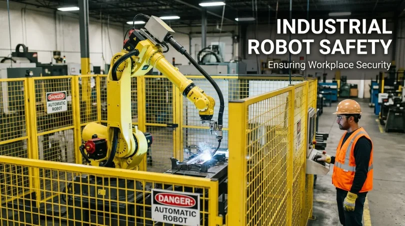

Industrial robot safety is the combination of engineering controls, safety procedures, risk assessments, and worker training used to prevent injuries around robotic systems. The biggest risks include unexpected robot movement and workers entering a robot’s operating area during maintenance, programming, or fault recovery. Effective robot safety requires physical guarding or safety-rated sensors, proper lockout/tagout, a documented risk assessment based on applicable standards such as ISO 10218:2025 or ANSI/A3 R15.06-2025, and hands-on worker training.
Why Robot Safety Is Urgent Right Now
Global industrial robot installations hit over 4.2 million units by 2023 and are growing faster than safety training programs can keep pace with. Automotive factories, logistics warehouses, electronics assembly lines, and food processing plants are all deploying robots at scale often faster than their safety infrastructure can scale to match.
Two events from recent years illustrate what the data already shows. At Tesla’s Fremont, California facility, a robotics technician filed a lawsuit claiming he was knocked unconscious when an industrial robot arm struck him during a maintenance window. At Tesla’s Austin Gigafactory, a reported incident involving a robot engineer drew national coverage and highlighted the gap between deployment speed and safety validation. These are not freak accidents. They follow a consistent pattern: humans in the robot’s workspace, under time pressure, in conditions where energy isolation was incomplete or bypassed.
BMW Group is currently deploying Figure.03 humanoid robots at its Landshut plant and running humanoid pilots across multiple European facilities. Toyota contracted seven Agility Robotics humanoid robots for a Canadian factory in early 2026. ABB, KUKA, Fanuc, and Yaskawa are collectively shipping tens of thousands of industrial robot units per year. The technology is outpacing the safety frameworks in many facilities and the injury data reflects it.
The Robot Cell: What a Safe Layout Actually Looks Like
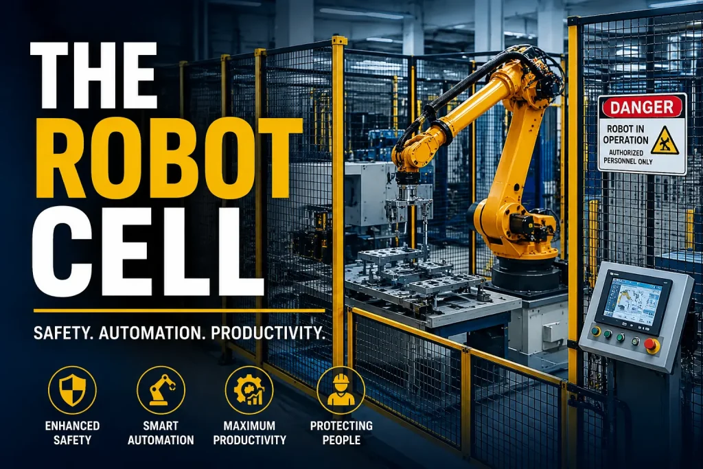
Most injury-prevention failures can be traced to layout decisions made at the design stage. The diagram below shows the key zones, access controls, and safety devices in a correctly designed industrial robot cell.
ROBOT CELL LAYOUT DIAGRAM
| 🔴 RESTRICTED / PROHIBITED ZONE Perimeter fencing or hard guard. No human entry during operation. 🟠 WORK ENVELOPE Maximum robot reach area. Contains the robot arm and base mount. 🔵 SAFETY ZONE (laser scanner) Active detection area. Robot slows or stops when worker detected. 🟢 COLLABORATIVE ZONE (cobot only) Shared human-robot workspace. Speed & separation monitoring or PFL active. 🟣 OPERATOR WORK AREA Safe station outside all hazard zones. | RESTRICTED / PROHIBITED ZONE (hard guarding)WORK ENVELOPE ROBOT ARM (base mount)⛔ E-STOP🚪 INTERLOCKED GATE⛔ E-STOP – SAFETY ZONE (laser scanner) ═══ COLLABORATIVE ZONE (cobot only) ═══ OPERATOR WORK AREA LIGHT CURTAINLIGHT CURTAIN ⛔ E-STOP⛔ E-STOP⛔ E-STOP⛔ E-STOP |
Key design rules to remember:
- The robot’s work envelope (maximum reach during any programmed task) must be fully contained within the restricted zone.
- Emergency stops must be located outside the restricted zone and at the operator station. ISO 13850 governs E-stop design and placement.
- Interlocked gates must bring the robot to a safe stop state before the gate can be fully opened, not after.
- The operator work area must be separated from the restricted zone by a physical barrier, light curtain, or area scanner depending on the application.
- Safety zone boundaries for laser-scanner-based cells must be validated to account for scanner detection gaps at floor level and at heights above the scanner’s field of view.
Safety Zone Hierarchy
Industrial robot installations define three concentric zones, each with different entry rules and required controls.
🔴 PROHIBITED ZONE Outermost boundary
- Robot in full automatic operation
- No human entry permitted during any production cycle
- Hard guard or active safety device required at all boundaries
🟠 RESTRICTED ZONE Inside prohibited zone
- Robot work envelope plus tooling reach
- Entry requires: robot in verified safe state
- Full LOTO procedure mandatory before maintenance entry
🟢 COLLABORATIVE ZONE Cobot cells only
- Shared human-robot workspace
- Speed & separation monitoring (SSM) OR power & force limiting (PFL) must be active
- Application-specific risk assessment required and documented
OSHA’s Framework: No Robot Standard Exists Three Critical Standards Do
OSHA has no dedicated industrial robot standard as of 2026. The agency applies existing General Industry standards to robotic installations, and OSHA inspectors cite these when investigating incidents:
- 29 CFR 1910.147 (Control of Hazardous Energy / Lockout-Tagout): The standard most cited in robot-related fatality investigations. Requires identification and isolation of all energy sources before workers enter a robot cell for maintenance.
- 29 CFR 1910.212 (Machine Guarding): Requires physical guarding on machines with moving parts that present hazards to workers. Applies directly to robot cell perimeter design.
- 29 CFR 1910.119 (Process Safety Management): Applies when robotic systems handle highly hazardous chemicals above threshold quantities.
- OSHA Technical Manual, Section IV, Chapter 4 (updated September 2021): Primary field reference for OSHA inspectors. Covers hazard recognition, safeguarding, and investigation guidelines.
The General Duty Clause (Section 5(a)(1)) is also available to OSHA inspectors when a recognized hazard exists and no adequate controls are in place, even without a specific standard violation.
The 2025/2026 Standards Landscape: What Changed
Two landmark standards were published in 2025 that every robot safety professional needs to know. ISO 10218:2025 and ANSI/A3 R15.06-2025 now align for the first time, creating a unified global-U.S. framework.
ISO 10218:2025 (Parts 1 and 2)
Published February 2025, this was the first major revision to the global industrial robot safety standard since 2011. Three significant changes affect real-world deployments:
- Collaborative robot requirements previously in ISO/TS 15066:2016 are now integrated into the main standard.
- Cybersecurity is now an explicit requirement robot controllers connected to networks must be assessed for cybersecurity risks as part of the safety risk assessment.
- Functional safety requirements (Performance Level per ISO 13849; Safety Integrity Level per IEC 62061) are more clearly defined for robot safety control functions.
ANSI/A3 R15.06-2025
The newly revised American National Standard for industrial robots. Published after nearly eight years of development, it now harmonizes with ISO 10218:2025 for the first time. U.S. facilities can now align to a single global framework rather than managing divergent domestic and international requirements.
| Standard | Jurisdiction | Scope | Latest Version |
|---|---|---|---|
| ISO 10218-1 / 10218-2 | International | Robot design + robot cells | 2025 |
| ANSI/A3 R15.06 | United States | Industrial robots + systems | 2025 |
| ISO/TS 15066 | International | Collaborative robots (PFL validation) | 2016 (absorbed into ISO 10218:2025) |
| ISO 13849-1 | International | Safety-related control systems (Performance Level) | 2023 |
| IEC 62061 | International | Functional safety / SIL for machinery | 2021 |
| NFPA 79 | United States | Electrical standard for industrial machinery | 2021 |
Six Primary Hazard Categories: Where Injuries Actually Happen
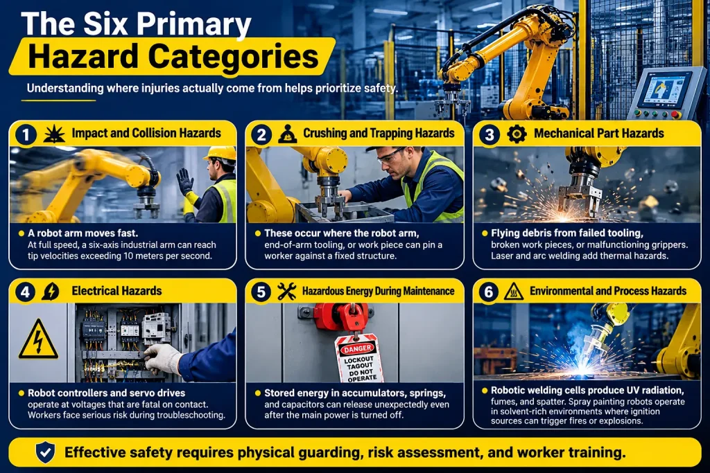
Understanding where injuries cluster helps prioritize spending and training. OSHA’s Technical Manual and CDC fatality data consistently point to the same patterns.
1. Impact and collision hazards. A six-axis industrial robot arm from ABB, KUKA, Fanuc, or Yaskawa can reach tip velocities exceeding 10 meters per second at full speed. Workers struck during programming, teaching, or fault recovery face severe blunt-force injury. The industrial manipulator does not slow down because a human entered the work envelope it executes its programmed path until a safety device intervenes or the arm makes contact.
2. Crushing and trapping hazards (pinch points). These occur where the robot arm, end-of-arm tooling, or work piece can pin a worker against a fixed structure, the cell floor, or another machine. Normal operating cycles in welding, stamping, and press-tending applications create lethal pinch-point geometry as a routine feature of production.
3. Mechanical part and process hazards. Flying debris from failed tooling, broken work pieces, or malfunctioning servo motor drives. Arc welding cells add UV radiation and fume exposure. Laser cutting applications require a separate laser safety hazard zone assessment. Paint robot installations in facilities like BMW and Toyota spray shops require NFPA 33 compliance for solvent-atmosphere ignition hazards.
4. Electrical hazards. Robot controllers and servo drive cabinets operate at voltages fatal on contact. Workers performing electrical troubleshooting without proper arc-flash protection face serious risk. Servo drive capacitors hold lethal charge for a manufacturer-specific duration often 3 to 10 minutes after the main disconnect is opened.
5. Stored energy hazards during maintenance. This is where the fatality data clusters. Hydraulic accumulators, pneumatic lines, counterbalance spring systems, and servo drive capacitors all represent stored energy that can release unexpectedly after the main power disconnect has been opened. “I turned off the power” is not the same as “I isolated all energy sources.”
6. Environmental hazards in collaborative zones. Workers in shared human-robot workspaces adjacent to high-production robotic cells face ergonomic risks not captured in robot injury statistics. The production pace set by industrial automation creates repetitive-motion demands on humans who feed parts, inspect outputs, or perform secondary operations.
Safeguarding Methods: Choosing the Right Tool for the Application
Choosing the wrong safeguarding method for an application is as dangerous as using no safeguarding at all.
| Safeguarding Method | Best Application | Relative Cost | Safety Performance | Key Limitation |
|---|---|---|---|---|
| Hard perimeter guarding (fencing) | High-speed welding, stamping, heavy payload robots | Medium | Excellent (PLe / SIL3 possible) | Workers often prop gates open; restricts flexible access |
| Interlocked access gates | All caged cells requiring periodic human entry | Low (add-on to fencing) | High (PLd/PLe with safety relay or safety PLC) | Gate-bypass is the most common OSHA violation |
| Light curtains | Packaging, palletizing, machine tending with frequent access | Medium | High (PLe / SIL3 rated units available) | Muting logic can create blind spots if misconfigured |
| Area laser scanners | Assembly cells, cobots, AGV intersections | Medium-High | High (PLd typical; PLe with dual scanner) | Floor-level gaps; reflective surfaces cause detection errors |
| Safety-rated vision systems | Flexible manufacturing, mixed human-robot zones | High | Medium-High (application-dependent) | Requires validation testing; sensitive to lighting changes |
| Power-and-force limiting (PFL) | Collaborative assembly, inspection, small parts handling | Low (built-in to cobots) | Application-dependent | Only valid when tooling and work piece are also non-hazardous |
Safety PLC vs. safety relay: For cells with multiple safety devices (light curtains, area scanners, interlocked gates, E-stops), a safety PLC provides programmable logic validated to PLd or PLe under ISO 13849. A safety relay handles simpler two-channel circuits. Using a standard PLC for safety functions common in older industrial control systems does not meet ISO 13849 requirements.
Performance Level (PL) and Safety Integrity Level (SIL) are the two parallel frameworks for quantifying safety function reliability. ISO 13849 uses PL (PLa through PLe); IEC 62061 uses SIL (1 through 3). For robot cell safety functions, PLd or PLe is typically required corresponding to SIL 2 or SIL 3. These require documented calculations of Mean Time to Dangerous Failure (MTTFd) for every component in the safety chain.
Lockout/Tagout for Robot Cells: The Full Procedure
LOTO for a robotic cell is more complex than LOTO for a conventional machine. The procedure must account for all stored energy, not just the main electrical disconnect.
LOCKOUT / TAGOUT WORKFLOW ROBOTIC CELL
NOTIFY
Inform all affected workers that maintenance is beginning and the robot cell will be de-energized.
IDENTIFY ALL ENERGY SOURCES
Main electrical disconnect, pneumatic supply valves, hydraulic accumulator circuits, gravity-loaded axes (counterbalance systems), servo drive capacitors.
SHUT DOWN THE ROBOT
Complete the current cycle, then initiate a controlled shutdown from the operator station or teach pendant.
ISOLATE AND LOCK ALL ENERGY SOURCES
Apply personal lock and tag to each isolation point. One lock per authorized worker entering the cell.
RELEASE STORED ENERGY
Bleed pneumatic lines to atmosphere. Discharge hydraulic accumulators per SOP. Wait the manufacturer-specified capacitor discharge time (check robot manual: typically 3 to 10 minutes). Block or support any gravity-loaded robot axes.
VERIFY DE-ENERGIZATION MOST OFTEN SKIPPED
Attempt to start the robot from the teach pendant. Confirm: no motion, no pressure, no voltage present. This step is most often skipped and is the step that saves lives.
PERFORM MAINTENANCE
Work can now begin safely inside the robot cell.
RESTORE ENERGY
Clear all tools and personnel from the cell. Remove locks and tags in reverse order. Notify all affected workers before restart.
Critical reminder: An E-stop is a protective stop, not an energy isolation device. A robot in E-stop state is still fully energized. Another worker at a remote station, a control system fault recovery, or a PLC program restart can release the stop condition without warning.
Risk Assessment Flowchart
ISO 12100 and ISO 10218:2025 require a systematic risk assessment before a robot cell is placed into service. The hierarchy is mandatory: design changes first, then safeguarding, then training and information.
RISK ASSESSMENT PROCESS ISO 12100 / ISO 10218:2025
STEP 1: DEFINE THE ROBOT SYSTEM
All operating modes: automatic, manual, teaching, maintenance, fault recovery, emergency
▼
STEP 2: IDENTIFY ALL HAZARDS
Motion, energy sources, process hazards, ergonomic risks, cybersecurity, and access scenarios
▼
STEP 3: ESTIMATE INITIAL RISK
Severity of potential injury ✕ Probability of occurrence ✕ Possibility of avoidance
▼
STEP 4: APPLY RISK REDUCTION (in this order)
① Inherently safe design always first
② Safeguarding and protective devices
③ Information, warnings, and training
▼
STEP 5: VERIFY RISK REDUCTION MEASURES
Test every safety function works as designed under realistic production conditions
▼
Residual risk IS tolerable
Proceed to documentation and sign-off
Residual risk is NOT tolerable
Return to Step 4 and apply additional risk reduction measures
STEP 6: DOCUMENT AND SIGN OFF
Record all hazards, measures, and residual risk justification. Update whenever program, tooling, or layout changes.
A risk assessment is a live document, not a one-time checklist. Universal Robots, ABB, and KUKA publish risk assessment templates for their platforms, but using a manufacturer template does not substitute for an application-specific analysis.
Collaborative Robot Safety: Where Deployments Go Wrong
Universal Robots (UR3e, UR5e, UR10e, UR20), Fanuc’s CRX series, and ABB’s GoFa and SWIFTI lines are expanding cobot deployments across automotive, electronics, and logistics sectors. The growth is justified. But the marketing around cobots has created a dangerous misconception: that a cobot is inherently safe without guarding.
ISO/TS 15066 and ISO 10218:2025 are explicit on this point: the collaborative operation mode must be validated for the complete application, including the end-of-arm tooling, the work piece, and the specific body regions that could be contacted. A Universal Robots conformity certificate covers the robot platform. It says nothing about whether your specific application is safe.
The Four Collaborative Operation Modes (ISO/TS 15066 / ISO 10218:2025)
- Safety-rated monitored stop (SMS): Robot stops when human enters the collaborative workspace. Simplest mode; slowest for throughput.
- Hand guiding: Worker physically guides the robot to teach positions. Requires a hand-guiding device with its own E-stop.
- Speed and separation monitoring (SSM): Robot slows as the worker approaches and stops at the minimum protective separation distance. Requires area scanners or safety cameras.
- Power and force limiting (PFL): Robot stops on contact when force exceeds the ISO/TS 15066 Annex A body-region thresholds. Most commonly associated with cobots like UR, Fanuc CRX, and ABB GoFa.
Common cobot deployment errors in 2026:
- Installing a PFL cobot and removing all guarding before completing the application risk assessment.
- Using PFL mode when the end-of-arm tooling or work piece creates a sharp, thermal, or injection hazard that the robot’s force sensor cannot prevent.
- Assuming the cobot’s rated payload force limit equals the ISO/TS 15066 contact force limit. They are different quantities, calculated differently.
- Skipping biomechanical validation of the specific contact scenario.
You May Also Like It:
MIG vs TIG Welding: Complete Guide to Differences and Procedures
CNC Machining Tolerances: The Complete Expert Guide
Xcel Power Shut Off: Everything You Need to Know About PSPS Outages
Power to Choose in Texas: The Complete Guide to Comparing Electricity Plans
PPE Requirements by Robot Cell Type
Personal protective equipment is the last layer of protection, applied after engineering controls and administrative procedures have already reduced the risk as far as practicable.
| Cell Type | Required PPE | Regulatory Basis |
|---|---|---|
| Welding cells (ABB, Fanuc, KUKA welding robots) | Safety glasses (welding shade lens for adjacent workers), hearing protection if >85 dBA, flame-resistant clothing where spatter risk, steel-toed footwear | 29 CFR 1910.132, ANSI Z87.1 |
| Assembly / cobot cells (UR, CRX, GoFa) | Safety glasses (impact-rated), cut-resistant gloves for sharp part handling, steel-toed or composite-toe footwear, hi-vis vest in open floor areas | 29 CFR 1910.132, ANSI Z87.1 |
| Maintenance entry (all cell types) | Arc-flash rated PPE for electrical work, hard hat if overhead hazards present, face shield, insulating gloves (Class 0 minimum for control voltage), personal lock and tag (not optional) | 29 CFR 1910.147, NFPA 70E |
PPE requirements must be established through a documented hazard assessment under 29 CFR 1910.132, not assumed. The assessment must be certified by the employer.
Real-World Incidents: What the Case Files Show
Tesla, Fremont and Austin (2024-2026): Multiple documented incidents at Tesla’s highly automated Gigafactories follow the maintenance-window hazard pattern. A robotics technician at the Fremont facility filed a lawsuit claiming he was knocked unconscious by a robot arm during a maintenance operation, seeking $51 million in damages. A separate reported incident at the Austin Gigafactory involved an engineer inside a robot’s workspace during fault-clearing. In both cases, the worker was inside the work envelope in a partially powered state the exact scenario that LOTO is designed to prevent.
BMW Group: BMW operates some of the most densely automated assembly lines in the automotive industry, running KUKA robots throughout its facilities. Its current humanoid robot pilots at Plant Landshut (Figure.03 deployment, 2026) and Plant Leipzig represent the frontier of human-robot collaboration at scale. BMW has publicly acknowledged the challenge of managing safety validation timelines alongside rapidly evolving robot capabilities, particularly as humanoid robots enter spaces not designed with traditional robot safety zones in mind.
Toyota: Toyota’s 2026 deployment of Agility Robotics humanoid units in its Canadian factory marks a new category of industrial robot safety challenge. Humanoid robots that walk, carry parts, and navigate shared human spaces do not fit cleanly into the ISO 10218 framework designed around fixed-base industrial manipulators. Safety teams at Toyota and other early humanoid adopters are working ahead of the available standards.
ABB Robotics: ABB has developed its SafeMove2 technology, which provides safety-rated speed and position monitoring functions within the robot controller itself, enabling Performance Level d safety functions without external safety PLCs for certain applications. ABB’s GoFa cobot and SWIFTI high-speed cobot demonstrate that manufacturer-integrated functional safety can reduce deployment complexity when properly validated.
KUKA: KUKA’s LBR iiwa collaborative industrial manipulator is in use at BMW, Volkswagen, and several aerospace facilities in Europe. KUKA’s experience with cobot deployment at scale helped inform many of the practical force-limit validation approaches now referenced in ISO/TS 15066 and integrated into ISO 10218:2025.
Cybersecurity as a Safety Dimension: The 2025 Addition
This is the most underrepresented risk in industrial robot safety discussions and ISO 10218:2025 now requires it in the risk assessment scope.
Modern robot controllers from Fanuc (R-30iB Plus), KUKA (KRC5), and ABB (OmniCore) run on real-time operating systems connected to facility networks. Remote access for programming, monitoring, and maintenance is standard. Some installations push data to cloud platforms for predictive maintenance analytics.
What a compromised robot controller can do:
- Speed limits raised above safe operating parameters without warning.
- Safety zone definitions modified to shrink the protective zone.
- Emergency stop logic disabled in the industrial control system.
- Robot program modified to execute unintended motions during production.
Practical cybersecurity controls for robot safety:
- Robot controllers on isolated network segments (VLAN at minimum), not the general corporate LAN.
- Remote access requiring multi-factor authentication and VPN, not open RDP or Telnet ports.
- Safety function parameters access-controlled; changes require authorization and audit logging.
- Robot controller firmware tracked and updated on a defined maintenance schedule.
- Incident response plan that includes robot controller compromise as a scenario.
Worker Training: What “Trained” Actually Means
Training is the last layer of defense, not the first. But inadequate training in robotic facilities is a documented contributor to incidents, particularly in facilities deploying robots for the first time.
Effective training for workers interacting with robot cells must include:
- What the robot is programmed to do in each operating mode and when it will move.
- The conditions that cause unexpected motion: fault recovery sequences, sensor errors, program restarts initiated from remote stations.
- Location and operation of every emergency stop in the cell and in adjacent areas.
- The cell-specific LOTO procedure, practiced hands-on with the actual cell, not demonstrated on a slide or video.
- How to recognize and report near-misses without fear of blame or reprisal.
Near-miss reporting culture is a leading safety indicator. Facilities where workers feel safe reporting close calls collect the data needed to prevent actual injuries. Facilities where workers fear reprisal for reporting near misses are accumulating unreported incidents until one becomes fatal. OSHA’s Voluntary Protection Program (VPP) and ANSI Z10.0 workplace safety management systems both treat near-miss reporting rates as evidence of safety program maturity.
Fanuc America and Universal Robots both offer formal operator and maintenance training programs specific to their platforms. These are worthwhile, but they cover the robot not the application. Application-specific training must be developed by the integrator or the facility, not delegated to the robot manufacturer.
Authoritative References and Standards
Regulatory:
- OSHA Technical Manual (OTM), Section IV, Chapter 4: Industrial Robot Systems and Industrial Robot System Safety (Updated September 2021) osha.gov
- 29 CFR 1910.147: Control of Hazardous Energy (Lockout/Tagout) osha.gov
- 29 CFR 1910.212: Machine Guarding osha.gov
- OSHA Robotics Hazard Recognition osha.gov/robotics
Safety Standards:
- ISO 10218-1:2025 / ISO 10218-2:2025: Robotics Safety requirements iso.org
- ANSI/A3 R15.06-2025: Industrial Robots and Robot Systems Safety Requirements (USA) automate.org
- ISO/TS 15066:2016: Collaborative robots (PFL validation) iso.org
- ISO 13849-1:2023: Safety of machinery Safety-related parts of control systems (Performance Level) iso.org
- IEC 62061:2021: Safety of machinery Functional safety (SIL) iec.ch
- NFPA 79:2021: Electrical Standard for Industrial Machinery nfpa.org
- ISO 12100:2010: Safety of machinery General principles for design (Risk assessment) iso.org
Research:
- CDC: Robot-Related Fatalities at Work in the United States, 1992–2017 stacks.cdc.gov
- Applied Ergonomics (2024): Robot-related injuries in the workplace sciencedirect.com
Frequently Asked Questions
What is the primary OSHA standard for industrial robot safety?
OSHA does not have a dedicated robot safety standard as of 2026. Compliance is governed by several existing General Industry standards: 29 CFR 1910.147 (Lockout/Tagout) and 29 CFR 1910.212 (Machine Guarding) are cited most often in robot-related fatality investigations. OSHA’s Technical Manual Section IV, Chapter 4 is the key field guidance document inspectors use.
What is ISO 10218:2025 and why does it matter?
ISO 10218:2025 (Parts 1 and 2) is the international safety standard for industrial robots and robot cells, published February 2025. It is the first major revision since 2011. Three key changes: integration of collaborative robot requirements from ISO/TS 15066, explicit cybersecurity requirements as part of the safety risk assessment, and tightened documentation standards. It now aligns with ANSI/A3 R15.06-2025, creating a unified global-U.S. framework for the first time.
What is the difference between Performance Level (PL) and Safety Integrity Level (SIL)?
Both quantify how reliably a safety function performs. Performance Level (PLa through PLe) comes from ISO 13849 and is common in European-origin machinery standards. Safety Integrity Level (SIL 1 through 3) comes from IEC 62061 and originates in process safety. For robot cell safety functions, PLd or PLe is typically required corresponding to SIL 2 or SIL 3. Both require documented calculations, not just component selection from a catalog.
Are cobots safe without physical guarding?
Not automatically. A collaborative robot certified to ISO 10218:2025 has been designed to support safe collaborative operation. Whether any specific application is safe without guarding depends entirely on the application risk assessment. If the end-of-arm tooling, work piece, or process creates hazards independent of the robot’s force limit, physical guarding or additional protective measures may still be required.
What are the most common violations cited in robot-related OSHA inspections?
Lockout/tagout violations (29 CFR 1910.147) are the most common citation in robot-related fatal incident investigations. These include missing written LOTO procedures, failure to identify all energy sources (particularly stored energy in pneumatic lines and servo drive capacitors), not verifying de-energization before cell entry, and LOTO bypass during troubleshooting under time pressure.
What changed in the American robot safety standard in 2025?
ANSI/A3 R15.06-2025, published after nearly eight years of development, is the first U.S. robot safety standard to harmonize with ISO 10218:2025. Key changes include explicit coverage of collaborative robot applications, cybersecurity requirements, and alignment with the international standard for the first time eliminating the need for facilities to manage divergent domestic and international compliance requirements.
How does cybersecurity affect industrial robot safety?
ISO 10218:2025 explicitly includes cybersecurity in the robot safety risk assessment scope. A compromised robot controller can have speed limits raised, safety zone definitions altered, or emergency stop logic disabled through network-based attacks. Practical controls include network segmentation for robot controllers, multi-factor authentication for remote access, access control for safety parameter changes, and current firmware on all robot control systems.
What should a robot-specific LOTO procedure include that a standard machine LOTO does not?
Three energy sources not present in most conventional machine LOTO procedures: servo drive capacitors (which hold lethal charge for 3 to 10 minutes after main power disconnect), gravity-loaded robot axes that can drop under their own weight if the counterbalance system fails, and pneumatic or hydraulic circuits used by end-of-arm tooling separately from the robot’s main power systems. Verification of de-energization by attempting to start the robot from the teach pendant before cell entry is also required and is the step most often skipped.
You May Also Like It:
ZNOG Stock: Complete Investor Guide to Zion Oil & Gas (OTCMKTS: ZNOG)
Oil Smells Like Gas? 7 Causes, Warning Signs, and Fixes
Public Power Energy Supplier: What It Is and How It Works
Steel Grade: The Complete Guide to Understanding Every Type of Steel





[…] Industrial Robot Safety: The Complete 2026 Guide for Facilities, Engineers & Safety Managers […]