
What Are CNC Machining Tolerances?
Every CNC machined part exists in the real world, not on a blueprint. And the real world is imperfect.
No matter how advanced a CNC machine is, it cannot reproduce a dimension with absolute mathematical perfection on every single cycle. There will always be a tiny deviation between what the design specifies and what the machine actually produces. The question is: how much deviation is acceptable before the part stops functioning correctly?
That answer is defined by CNC machining tolerances.
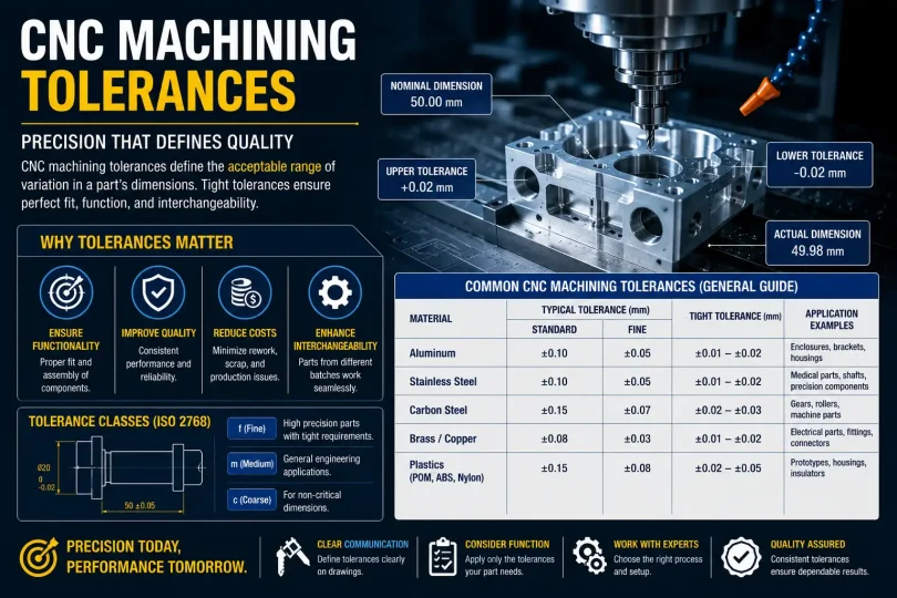
In precision manufacturing, a machining tolerance is the permissible range of dimensional variation for a feature on a machined part. It defines the upper limit (maximum allowable size) and the lower limit (minimum allowable size) for any given dimension. As long as the final part falls within this band, it passes quality inspection and is considered acceptable for its intended use.
To put it in concrete terms: if a shaft is specified as 25.00 mm with a tolerance of ±0.10 mm, the manufactured part is acceptable anywhere between 24.90 mm and 25.10 mm. Anything outside that range is rejected.
Tolerances serve three core purposes in manufacturing:
Form refers to how closely the shape of the part matches the design geometry. Fit refers to how well a part interfaces with its mating component. Function refers to whether the assembly performs as intended during actual use. Tolerances protect all three of these outcomes simultaneously.
Setting tolerances incorrectly in either direction creates serious problems. Tolerances that are too loose result in parts that do not fit together, assemblies that vibrate or leak, and products that fail prematurely. Tolerances that are unnecessarily tight drive up manufacturing costs, extend lead times, increase scrap rates, and often provide zero functional benefit to the end product.
The skill of specifying tolerances correctly is one of the most valuable and underappreciated disciplines in mechanical engineering and product design.
The Tolerance Band: Understanding Upper Limits, Lower Limits, and Allowable Variation
Before exploring the different types of tolerances, it is important to understand the fundamental vocabulary that machinists and engineers use every day.
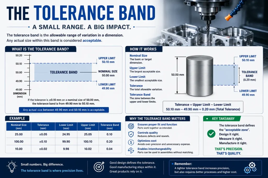
Basic Size (Nominal Size): The theoretical dimension shown on the engineering drawing. This is the target the machinist aims to hit.
Upper Limit: The maximum acceptable dimension for the feature. Also called the upper deviation.
Lower Limit: The minimum acceptable dimension for the feature. Also called the lower deviation.
Tolerance Band (Tolerance Zone): The total range between the upper and lower limit. A tight tolerance band means a small difference between the two limits. A loose tolerance band means a large difference.
Actual Size: The measured dimension of the finished part after machining. This must fall within the tolerance band to be accepted.
Allowance: The intentional difference between mating parts in an assembly, designed to ensure proper clearance or interference.
Bonus Tolerance: In GD&T contexts, an additional tolerance that becomes available when a feature departs from its Maximum Material Condition (MMC).
Consider this practical example. A CNC machine shop is producing a precision pin with a nominal diameter of 10.00 mm. The engineer specifies a tolerance of ±0.05 mm. This means:
Upper limit = 10.05 mm. Lower limit = 9.95 mm. Tolerance band = 0.10 mm.
Any pin measuring between 9.95 mm and 10.05 mm passes inspection. A pin measuring 9.94 mm or 10.06 mm is out of tolerance and must be scrapped or reworked.
Types of CNC Machining Tolerances: A Detailed Breakdown
CNC machining tolerances are not a single, monolithic concept. They come in several forms, each controlling a different aspect of part geometry. Understanding these distinctions is essential for writing effective engineering drawings and communicating clearly with your machine shop.
Bilateral Tolerances
A bilateral tolerance permits dimensional variation in both directions from the basic size. The allowable variation is applied equally or unequally above and below the nominal value.
Equal bilateral example: a hole diameter of 20.00 mm ±0.10 mm. The acceptable range is 19.90 mm to 20.10 mm.
Unequal bilateral example: a shaft diameter of 15.00 mm +0.05 / -0.02 mm. The acceptable range is 14.98 mm to 15.05 mm. This type is used when the function of the part requires more clearance in one direction than the other.
Bilateral tolerances are the most commonly used format in general CNC machining because they are intuitive, easy to verify, and apply naturally to most part features.
Unilateral Tolerances
A unilateral tolerance allows variation in only one direction from the basic size — either entirely positive or entirely negative, but never both.
For example: a pin with a basic diameter of 12.00 mm and a unilateral tolerance of +0.10 mm / 0.00 mm. This means the pin can be up to 12.10 mm but must not be smaller than 12.00 mm. The basic size is the lower limit in this case.
Unilateral tolerances are particularly useful when a feature must always remain on one side of its nominal value for assembly reasons. They are common in press fit applications, interference fits, and cases where a minimum or maximum wall thickness is safety-critical.
Limit Tolerances
A limit tolerance specifies the actual maximum and minimum dimensions directly on the drawing, without requiring any calculation.
Example: a bore diameter shown as 18.95 / 19.05 mm. The inspector checks whether the measured dimension falls between those two numbers. There is no need to calculate upper or lower deviations from a nominal value.
Limit tolerances are popular in precision manufacturing because they simplify shop floor inspection. The machinist or quality engineer simply compares the measured value against the stated limits with no intermediate math.
Linear Tolerances
Linear tolerances control straight-line measurements including length, width, height, diameter, and depth. They represent the most fundamental category of tolerance in any machining drawing. ISO 2768 and ASME Y14.5 both provide extensive coverage of linear tolerances across different precision grades and nominal size ranges.
Angular Tolerances
Angular tolerances define the acceptable variation in angles between features. They are particularly important in parts with tapered surfaces, chamfers, angled holes, or compound geometries. Angular tolerances are often expressed in degrees and minutes, and they appear explicitly in ISO 2768 tolerance tables.
Geometric Tolerances (GD&T)
Geometric tolerances are the most comprehensive and powerful form of tolerance specification in modern manufacturing. They are defined through the Geometric Dimensioning and Tolerancing (GD&T) system, which uses a symbolic language standardized under ASME Y14.5 in the United States and ISO 1101 internationally.
GD&T moves beyond simple plus/minus notation to control the actual shape, orientation, location, and runout of part features. This makes it the preferred system for precision assemblies where controlling how a feature relates to other features is as important as controlling its size.
The primary categories of GD&T controls include:
Form controls govern the intrinsic shape of a single feature without reference to any datum. Flatness controls the deviation of a surface from a perfect plane. Straightness controls the deviation of a line element from a perfect straight line. Circularity (roundness) controls how closely a circular cross-section approximates a true circle. Cylindricity combines roundness, straightness, and taper control across the full length of a cylindrical feature.
Orientation controls define how a feature must be oriented relative to a datum reference frame. Perpendicularity controls the 90-degree relationship between a surface or axis and a datum. Parallelism controls equal distance between a surface or axis and a datum. Angularity controls a specific non-90-degree angular relationship to a datum.
Location controls specify where a feature must be positioned relative to datums. Position (True Position) is the most powerful and widely used GD&T control. It defines a cylindrical or parallel-plane tolerance zone within which the axis or center plane of a feature must lie. Profile of a surface and profile of a line control complex 3D shapes and curves. Concentricity and symmetry control the relationship between feature centers.
Runout controls are used for rotating parts. Circular runout controls variation when a part is rotated 360 degrees about its datum axis, measured at a single cross-section. Total runout extends this control across the full surface.
The significant advantage of GD&T over simple ± tolerances is that it accurately reflects real functional requirements. A simple ± diameter tolerance does not tell the machinist anything about where the center of a hole must be located relative to other holes or surfaces. A GD&T Position callout specifies exactly that, which is far more useful for ensuring assembly fit.
CNC Machining Tolerance Standards: ISO 2768 and ASME Y14.5
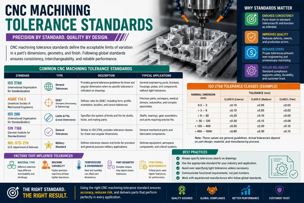
Two major international frameworks govern how tolerances are specified and interpreted in CNC machining. Engineers who understand these standards communicate more clearly with suppliers, reduce drawing errors, and avoid costly misunderstandings.
ISO 2768: General Tolerances for Linear and Angular Dimensions
ISO 2768 is an international standard that provides default tolerances for dimensions that are not explicitly toleranced on an engineering drawing. It is divided into two parts.
ISO 2768-1 covers general tolerances for linear dimensions and angles. It establishes four tolerance classes based on increasing precision requirements. The class designation appears in the drawing title block, telling the machine shop what default tolerance applies to every un-toleranced dimension.
Class f (Fine): Designed for applications requiring high precision, such as aerospace structural components, medical instrument housings, and precision instrument parts. This class applies the tightest allowable variations for linear and angular dimensions.
Class m (Medium): The most widely used tolerance class in general manufacturing. It balances precision with economical production. Most automotive body parts, consumer electronics enclosures, and general mechanical assemblies use ISO 2768-m as their drawing default.
Class c (Coarse): Applied where looser dimensional control is acceptable and economical production is the priority. Sheet metal fabrication, structural castings, and large weldments often fall into this category.
Class v (Very Coarse): For rougher work where even the coarse tolerance is unnecessarily strict. Heavy fabrication and certain structural applications use this class.
ISO 2768-2 covers general geometric tolerances for features such as straightness, flatness, perpendicularity, symmetry, and circular runout. It uses three tolerance classes designated H (fine), K (medium), and L (coarse).
In practice, engineers write the combined designation in the drawing title block. For example, “ISO 2768-mK” means medium linear tolerances combined with medium geometric tolerances. This single notation replaces dozens of individual tolerance callouts and keeps the drawing clean and readable.
A critical point: ISO 2768 is a fallback standard. It fills in the blanks where tolerances are not explicitly stated. For critical features such as bearing bores, precision fits, and mating surfaces, explicit tolerance callouts always take precedence over the ISO 2768 defaults.
One important limitation of ISO 2768 is that it is primarily designed for regular geometric features. Complex 3D freeform surfaces, which are increasingly common in modern product designs, often require individual GD&T profile callouts rather than relying on ISO 2768 alone.
ASME Y14.5: The GD&T Bible
The American Society of Mechanical Engineers publishes ASME Y14.5, the definitive American standard for Geometric Dimensioning and Tolerancing. This standard defines the symbols, rules, and interpretation methods for all GD&T callouts used in US-based manufacturing and in industries that follow American engineering practices.
The most recent version is ASME Y14.5-2018. It is the standard required by aerospace suppliers under AS9100, defense contractors under MIL-STD, and medical device manufacturers working toward FDA compliance.
The key difference between ISO 1101 (the international GD&T standard) and ASME Y14.5 relates to how certain tolerances are interpreted, particularly the treatment of the datum reference frame and some feature control frame rules. Engineers working with international suppliers should clarify which standard governs the drawing to prevent misinterpretation.
Standard CNC Machining Tolerance Values: What to Expect in Practice
Understanding the theoretical framework of tolerances is important, but engineers and buyers also need practical numbers. What tolerances can a typical CNC machine shop actually hold, and what do those tolerances cost?
Standard CNC Tolerances
For most general-purpose CNC milling and turning operations, the standard default tolerance is approximately ±0.127 mm (±0.005 inches). This is the tolerance that most machine shops apply when no explicit tolerance is specified on the drawing.
This level of precision is achievable using standard CNC equipment with appropriate tooling and programming. It is suitable for clearance holes, non-mating surfaces, general structural features, and assembly components where fit and function do not require exceptional accuracy.
Precision CNC Tolerances
For applications requiring greater dimensional control, such as bearing seats, precision shaft fits, valve components, and instrument housings, CNC machine shops can typically hold tolerances in the range of ±0.025 mm (±0.001 inches) under controlled conditions.
Achieving this level of precision requires more careful setup, slower cutting speeds, finer finishing passes, and more rigorous inspection procedures. The cost per part increases accordingly.
High-Precision CNC Tolerances
For aerospace flight-critical components, high-performance automotive engine parts, precision optical instruments, and certain medical devices, tight tolerances in the range of ±0.005 mm (±0.0002 inches) or better may be specified.
At this level of precision, standard CNC machining approaches the limits of what is achievable with milling and turning alone. Temperature-controlled machine rooms, high-precision spindles, specialized cutting tools, coordinate measuring machine (CMM) verification, and secondary operations such as grinding or honing become necessary.
Ultra-Precision Tolerances
For surgical implants, semiconductor manufacturing equipment, and certain aerospace guidance components, extremely tight tolerances in the range of ±0.001 mm (±0.00004 inches) are occasionally required. These tolerances are rare in commercial production and demand specialized lapping, grinding, or ultra-precision turning centers operating under highly controlled environmental conditions.
Tolerance Reference Chart
| Tolerance Class | Typical Value | Application Examples | Cost Impact |
|---|---|---|---|
| Standard | ±0.127 mm (±0.005″) | Structural parts, non-mating surfaces | Baseline (1x) |
| Precision | ±0.025 mm (±0.001″) | Bearing seats, precision fits | Moderate increase (2-3x) |
| High Precision | ±0.005 mm (±0.0002″) | Aerospace, medical devices | Significant increase (5-10x) |
| Ultra-Precision | ±0.001 mm (±0.00004″) | Surgical implants, guidance systems | Very high (15x+) |
Going from ±0.005 inches to ±0.001 inches on a part typically adds 40 to 80 percent to the total machining cost. The relationship between tighter tolerances and cost is not linear but exponential. Small incremental tightening of tolerances at the loose end has relatively modest cost implications, but pushing into the sub-0.01 mm range causes machining costs to escalate sharply.
Factors That Affect Achievable CNC Machining Tolerances
A machinist’s ability to hold a specified tolerance is not determined by the machine alone. Multiple interacting factors influence the final dimensional accuracy of a CNC machined part.
Material Properties
The material being machined has a profound effect on achievable tolerances. Harder, more rigid materials such as tool steel, stainless steel, and titanium tend to maintain their shape during cutting and resist deflection, which supports tighter tolerances. However, hard materials also generate more heat during cutting and accelerate tool wear, which can introduce dimensional drift over a long production run.
Softer metals like aluminum and copper are easier to cut but may deform locally under cutting tool pressure, making tight tolerances harder to sustain consistently. Aluminum also has a relatively high coefficient of thermal expansion, meaning temperature variations in the machine shop can cause the workpiece to expand or contract enough to affect dimensions at tight tolerances.
Plastics present the greatest challenge for precision tolerances. Many engineering plastics such as nylon, PEEK, and polycarbonate are viscoelastic and exhibit creep under cutting forces. They are also sensitive to heat and moisture absorption, both of which cause dimensional instability. For standard plastic parts, ISO 2768-m is the general recommendation, while for metals and rigid composites, ISO 2768-f is commonly used.
CNC Machine Capability and Condition
The age, design, and maintenance condition of the CNC machine directly determine the baseline tolerance capability. High-precision CNC machining centers feature tighter spindle runout specifications, better thermal compensation systems, higher-resolution axis encoders, and stiffer frame construction. These characteristics all contribute to tighter, more repeatable tolerances.
Backlash in drive systems is a common source of dimensional variation. Drive screw wear, spindle bearing wear, and loose guide rail preloads all introduce positional uncertainty that the machine controller cannot fully compensate for. Regular preventive maintenance, including geometric calibration and thermal compensation updates, is essential to maintaining a machine’s rated tolerance capability.
Cutting Tools and Tooling Strategy
Tool wear is one of the most underappreciated contributors to tolerance drift in production machining. As a cutting insert or end mill wears, it begins to cut at a slightly different effective diameter. A tool worn by even 0.02 mm can push a previously in-tolerance feature out of specification.
Rigidity of the tool setup also matters significantly. Long tool overhangs increase deflection under cutting loads. Using the shortest possible tool extension for a given feature, balanced toolholders for high-speed operations, and shrink-fit or hydraulic toolholders for precision work all contribute to better tolerance control.
Thermal Effects and Environmental Conditions
Heat is the enemy of tight tolerances in CNC machining. The cutting process generates heat in the workpiece, the cutting tool, and the machine structure itself. As the machine warms up during a production shift, thermal growth in the spindle and frame can cause progressive dimensional drift.
High-precision machining centers address this with active thermal compensation systems that monitor temperature sensors throughout the machine and adjust axis positions mathematically. Precision machine shops also maintain temperature-controlled environments, typically at 20 degrees Celsius, to minimize workpiece expansion and contraction during and after machining.
For parts with very tight tolerances, thermal soak time after machining before final inspection is critical. A freshly machined aluminum part that has not yet stabilized to room temperature will measure differently than the same part measured 24 hours later.
Workpiece Fixturing and Setup
How a part is held during machining directly affects achievable tolerances. Insufficient clamping force allows the workpiece to shift under cutting loads. Excessive clamping force on thin-walled or delicate parts causes elastic deformation that springs back after unclamping, resulting in out-of-tolerance dimensions.
For parts requiring very tight tolerances, custom fixtures that distribute clamping forces evenly and provide precise datum location are often necessary. Dedicated soft jaws, precision vise stops, and fixture plates with accurately located dowel pins all contribute to repeatable part positioning across a production run.
Surface Finishes and Post-Processing
Engineers and buyers sometimes overlook the interaction between surface finish specifications and dimensional tolerances. Plating operations such as hard chrome plating, electroless nickel, or anodizing add material to the part surface, which changes the final dimension. A part machined to print that then receives 0.025 mm of hard chrome plating will be 0.025 mm larger on each plated surface.
For this reason, machining tolerances for plated or coated parts must account for the anticipated coating thickness. The drawing should clearly specify whether the stated tolerance applies before or after coating.
Industry-Specific Tolerance Requirements: What Different Sectors Demand
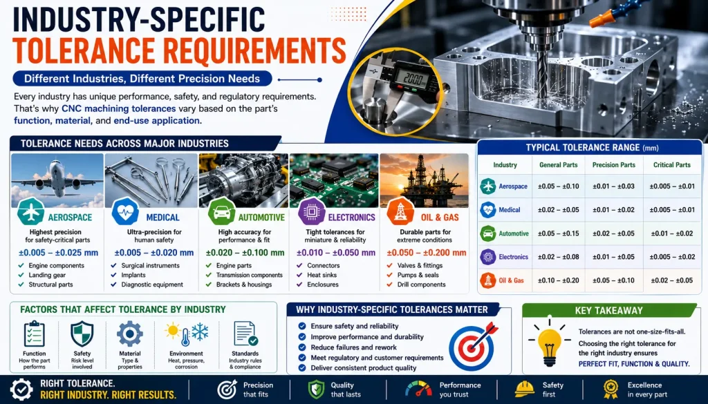
Different industries operate under vastly different precision requirements based on the consequences of dimensional failure in their specific applications.
Aerospace and Defense
The aerospace industry is often associated with extremely tight tolerances, and for critical components, this reputation is well-deserved. Turbine blades, engine cases, fuel system components, actuation mechanisms, and structural fittings in primary load paths are all machined to tight tolerances with rigorous inspection requirements.
However, it is important to recognize that not every aerospace component requires ultra-tight tolerances. Interior structural brackets, seat frame components, cabin panel fittings, and other non-critical parts often use ISO 2768-m as their general tolerance standard. Aircraft manufacturers manage their tolerance budgets carefully to ensure tighter specifications are reserved for components where they deliver real safety or performance value.
Aerospace CNC machining typically operates under AS9100 quality management system certification, which imposes strict requirements for process control, first article inspection, in-process inspection, and traceability of materials and operations.
Medical Devices and Surgical Instruments
Medical device manufacturing demands some of the tightest tolerances in any industry, and it carries the added complexity of regulatory oversight. Components that interact directly with human tissue, fluids, or bone must meet dimensional specifications with essentially zero margin for functional error.
Orthopedic implants such as hip stems, knee tibial trays, and spinal fusion cages are machined to tight tolerances on mating surfaces and articulating features. Cardiovascular device components, surgical instrument jaws and cams, and diagnostic instrument housings all require precision machining combined with meticulous quality documentation.
FDA 21 CFR Part 820 and ISO 13485 are the governing quality standards for medical device manufacturing. Both require comprehensive process validation, where the manufacturer demonstrates that the machining process consistently produces parts within specification under defined conditions.
Automotive Manufacturing
The automotive industry presents a wide spectrum of tolerance requirements within a single vehicle. Engine components such as crankshaft journals, cylinder bores, camshaft lobes, and connecting rod big end bores require tight tolerances to ensure proper oil film formation, minimize wear, and achieve target NVH (noise, vibration, harshness) performance.
However, body panels, brackets, seat frames, and other structural elements use much looser tolerances, often in the ±0.5 mm to ±1.0 mm range. Suspension components and chassis parts typically fall in between, with key mating surfaces held tighter while non-critical surfaces carry looser tolerances.
High-volume automotive CNC machining relies heavily on Statistical Process Control (SPC) to monitor dimensional variation in real time and detect process drift before out-of-tolerance parts are produced.
Electronics and Semiconductor Equipment
Modern electronic devices, particularly smartphones, tablets, and laptops, require precision machined components in their housings, lens assemblies, and structural chassis. The miniaturization trend in consumer electronics has driven tolerances for features like connector slots, camera module seats, and thermal interface surfaces into the sub-0.1 mm range.
Semiconductor manufacturing equipment represents one of the most demanding precision machining applications in any industry. Wafer handling components, stage mechanisms, and optical alignment structures must maintain tolerances in the single-digit micron range under thermal cycling, dynamic loads, and vibration. These components often require dedicated ultra-precision machining centers and cleanroom handling.
General Industrial and Commercial Manufacturing
The vast majority of CNC machined parts produced globally fall into the general industrial category, including pump bodies, valve housings, gearbox components, motor housings, hydraulic manifolds, and structural machine parts. These applications typically use standard tolerances of ±0.1 mm to ±0.5 mm for most features, with tighter tolerances specified only for critical sealing surfaces, bearing seats, and precision fits.
For this large and economically important sector, the priority is producing parts that function correctly and reliably at the lowest practical cost. Correctly specifying standard tolerances for non-critical features and reserving tighter callouts for the few features that genuinely need them is the most effective cost management strategy available to design engineers.
Fit Systems in CNC Machining: Clearance Fits, Interference Fits, and Transition Fits
One of the most important practical applications of CNC machining tolerances is the control of fits between mating components. The ISO 286-1 standard provides a comprehensive system for defining fits based on combinations of hole and shaft tolerances.
Clearance Fits
A clearance fit guarantees that the shaft will always be smaller than the hole, providing a defined gap between the mating surfaces. This gap allows the shaft to rotate freely within the bore, slide along its length, or permit thermal expansion without binding.
A running fit, such as H7/f7, provides sufficient clearance for continuous rotation under lubrication. H7/g6 provides a closer clearance suitable for precision sliding or low-speed rotation. Clearance fits are used in bearing applications (where the bearing itself creates the precision fit), sliding guideways, and assembly joints that must be assembled and disassembled repeatedly without damage.
Interference Fits (Press Fits)
An interference fit specifies a shaft that is intentionally larger than the hole. When the two parts are assembled by pressing or by thermal differential (heating the housing and cooling the shaft), the resulting interference creates a mechanical joint that resists both axial and rotational forces.
The H7/p6 fit provides a light press fit, used for bushings and pins that must be securely retained but may need occasional replacement. H7/s6 provides a medium interference fit suitable for gears pressed onto shafts. H7/u6 provides a heavy interference fit for permanent assemblies such as connecting rod bronze bushings.
For interference fits, CNC machining tolerances must be held very tightly, because the difference between a functional press fit and a loose slip fit can be as small as 0.02 mm in some size ranges.
Transition Fits
A transition fit falls between clearance and interference. Depending on where within the tolerance band the actual measured dimensions of the shaft and hole fall, the assembled fit might have a small clearance or a small interference. H7/k6 is a common transition fit used for precision locating pins and dowels where exact repeatability of position is required.
Tolerances and Cost: The Exponential Relationship Every Engineer Must Understand
Perhaps the most important practical insight in all of CNC machining tolerance specification is this: the cost of a machined part does not increase linearly as tolerances tighten. The relationship is exponential, and the cost inflection point occurs much sooner than most engineers expect.
The Cost Curve Explained
Loosening a tolerance from ±0.5 mm to ±0.25 mm has a relatively modest cost impact. The same machine, tools, and process can usually hold either tolerance with only minor adjustments to speeds, feeds, and inspection frequency.
However, tightening a tolerance from ±0.05 mm to ±0.01 mm can increase per-part cost dramatically. At this point, the machine shop must use slower cutting speeds and lighter finishing passes to minimize cutting forces and tool deflection. More frequent in-process inspection is required. Tool changes must happen more often to prevent dimensional drift from tool wear. Fixture rigidity becomes critical. Environmental temperature control may be necessary.
Tightening further to ±0.005 mm or tighter may require abandoning CNC milling or turning entirely and transitioning to secondary processes such as cylindrical grinding, surface grinding, jig boring, or honing. These are separate machines, separate setups, additional handling operations, and fundamentally different process economics.
Tightening a tolerance from ±0.005 inches to ±0.001 inches typically adds 40 to 80 percent to the machining cost on that feature. The cost of unnecessary tight tolerances compounds across every feature on a part and multiplies across the entire production volume.
The Most Common and Costly Design Mistake
Over-tolerancing is the single most common avoidable design error in CNC machined part specifications, according to experienced manufacturing engineers. Engineers sometimes assume that tighter tolerances automatically produce higher quality parts. This assumption is incorrect.
Part quality is ultimately demonstrated by the assembly performing its intended function reliably. A piston bore that is machined to an unnecessarily tight diameter tolerance while running in an engine block bored to standard tolerance gains nothing from that extra precision. The tight tolerance on the piston did not improve function; it simply increased cost.
The correct approach is to specify the loosest tolerance that still meets the functional requirement for each individual feature. This requires understanding what each dimension controls in the assembly and what consequences follow if it is at its maximum or minimum limit. Features that do not mate with other parts or control critical clearances should receive standard or coarse tolerances.
Practical Cost-Saving Tolerance Strategy
Add a general tolerance note to the title block of every drawing, such as “Unless otherwise specified: ±0.127 mm for all dimensions.” This establishes a clear standard tolerance for every un-called-out feature and prevents the machine shop from applying unnecessarily tight defaults.
Apply explicit tight tolerance callouts only to features that genuinely require them based on functional analysis. Bearing bores, sealing surfaces, mating faces, and precision pin holes typically need tighter callouts. Housing walls, bolt boss features, and general structural dimensions typically do not.
Consider GD&T position callouts instead of extremely tight ± diameter tolerances for hole location. A GD&T position tolerance defines a cylindrical tolerance zone around the true position of a hole, which is geometrically more correct and often allows a slightly larger total tolerance than an equivalent ± coordinate approach while still ensuring proper assembly.
When specifying tight flatness or straightness callouts for large surfaces or thin-walled parts, consult with the machine shop engineering team first. Internal material stresses released during machining can cause warping that makes certain geometric tolerances extremely difficult or impossible to hold without stress-relief operations or design modifications.
How to Measure and Inspect CNC Machining Tolerances
Specifying tolerances on a drawing is only half of the precision manufacturing equation. Measuring and verifying that machined parts actually comply with those tolerances is equally critical.
Hand Measurement Tools
For standard tolerances in the ±0.1 mm to ±0.5 mm range, experienced machinists use vernier calipers, digital calipers, and outside micrometers to verify dimensions efficiently on the shop floor. These tools, when properly calibrated and used correctly, provide accuracy to approximately ±0.01 mm.
Bore micrometers, telescoping gauges, and small hole gauges are used for internal diameter measurements. Depth micrometers measure pocket depths and step heights. Surface plates and precision squares provide reference surfaces for flatness and perpendicularity checks.
Gauge Pins and Ring Gauges
For high-volume production of cylindrical features, gauge pins (go/no-go pin gauges) and ring gauges provide fast, reliable, and repeatable pass/fail inspection. A go gauge must enter the bore; a no-go gauge must not. This binary decision is much faster than taking a measurement with a micrometer and comparing it to print limits, making gauge-based inspection ideal for production quantities.
Coordinate Measuring Machines (CMMs)
The CMM is the gold standard for dimensional inspection in precision CNC machining. A CMM uses a precision probe to contact defined points on a part and computes three-dimensional coordinates from those measurements. Software then compares the measured geometry against the nominal CAD model or drawing dimensions.
Modern CMMs can measure hundreds of features in a single automated inspection program, verify GD&T callouts such as true position, flatness, and perpendicularity to micron-level accuracy, and generate comprehensive inspection reports that provide full traceability for quality records.
CMM inspection is standard practice for first article inspection (FAI) reports in aerospace and medical device manufacturing, and it is used for ongoing production inspection of complex precision parts across all industries.
Optical and Vision-Based Inspection
Optical comparators project a magnified silhouette of a part onto a screen and compare it against an overlay template. This technique is fast and effective for checking external profiles, thread forms, and small features that are difficult to reach with contact probes.
Modern vision systems and non-contact laser scanners are increasingly used in precision manufacturing for high-speed dimensional verification of complex surfaces and contours. These systems can inspect an entire part surface in seconds, detecting dimensional deviations that would take hours to measure by hand.
Surface Roughness Measurement
Surface finish (roughness) is specified separately from dimensional tolerances but is closely related to part performance. Surface roughness is measured using a contact profilometer, which drags a diamond stylus across the surface and records the microscopic peaks and valleys. The most common roughness parameter is Ra, the arithmetic average of the absolute values of the surface height deviations.
Tight dimensional tolerances on bearing surfaces typically accompany requirements for smooth surface finish. A bearing bore machined to ±0.005 mm diameter tolerance would typically also specify a surface roughness of Ra 0.8 micrometers or better to ensure proper oil film formation and minimize wear.
Best Practices for Specifying CNC Machining Tolerances
Engineering teams that follow these principles consistently produce parts that meet functional requirements at lower cost and with fewer manufacturing problems.
Define functional requirements first. Before specifying any tolerance on a drawing, ask what each dimension controls in the assembly and what happens if it is at its extreme limit. Tolerances derived from functional analysis are always better justified than tolerances assigned by habit or convention.
Use the loosest tolerance that works. The tolerance should be tight enough to ensure the part functions correctly, and no tighter. Adding precision beyond what the application requires does not add quality. It adds cost.
Establish a general tolerance note in the title block. This prevents the machine shop from applying unnecessarily tight defaults to un-called-out dimensions. A clear general tolerance sets expectations and keeps costs under control.
Apply tight tolerances selectively. Reserve explicit tight tolerance callouts for critical features such as bearing bores, precision fit diameters, sealing surfaces, and locating features. Allow all other features to ride at the general tolerance.
Prefer GD&T for location and orientation. For controlling where a hole is located relative to other holes or features, a GD&T true position callout is geometrically superior to bilateral ± coordinate tolerances and often allows more manufacturing freedom while still ensuring functional fit.
Communicate with your machine shop early. Experienced machinists and manufacturing engineers can identify potential tolerance problems before production starts. Features that are difficult to machine, inspect, or fixture to the specified tolerance are better identified during design review than discovered after a batch of scrap.
Account for post-machining operations. If the part will be plated, coated, heat treated, or otherwise processed after CNC machining, the drawing must specify whether tolerances apply before or after processing. Coating thickness, dimensional changes from heat treatment, and surface geometry changes from shot peening must all be considered.
Validate your tolerances using tolerance stack-up analysis. In assemblies with multiple components, each individual part tolerance accumulates into an overall assembly variation. Performing a formal tolerance stack-up analysis, either worst-case or statistical (RSS), ensures that the sum of all part tolerances in the assembly stack still produces a functional result.
Common Tolerance Mistakes and How to Avoid Them
Even experienced engineers fall into recurring tolerance specification traps. Awareness of these common errors helps you avoid them.
Applying the same tight tolerance to every dimension. This dramatically overspecifies the part, inflates cost, and often provides no functional benefit. Every tight tolerance on a drawing must be justified by a functional reason.
Ignoring material behavior under machining forces. Thin-walled aluminum parts, long slender shafts, and large flat surfaces all behave in ways that make certain tolerances genuinely difficult to hold. A tolerance that looks reasonable on paper may be nearly impossible to achieve consistently in production.
Confusing surface finish with dimensional tolerance. A part can have tight dimensional tolerances but a rough surface finish, or smooth surface finish but loose dimensional tolerances. These are independent specifications. Specify both explicitly when both matter.
Failing to consider thermal effects on materials with high CTE. Aluminum expands approximately twice as much per degree of temperature change as steel. For tight-tolerance aluminum parts, temperature during machining, temperature during measurement, and temperature during assembly can all introduce dimensional discrepancies if not managed.
Specifying a tight geometric tolerance without defining the datum reference frame. A GD&T callout without proper datum references is ambiguous and unenforceable. Always establish a complete datum reference frame (primary, secondary, and tertiary datums) before assigning geometric tolerances.
Assuming the machine shop will figure it out. Clear, complete, unambiguous drawings are the foundation of good manufacturing outcomes. Ambiguous tolerances lead to variations between suppliers, inconsistency between production runs, and disputes over whether a part is acceptable.
Frequently Asked Questions About CNC Machining Tolerances
What is the standard tolerance for CNC machining?
The standard default tolerance for most CNC machining operations is approximately ±0.127 mm (±0.005 inches). Many shops work to ±0.1 mm as a standard baseline. High-precision operations can achieve ±0.025 mm (±0.001 inches) or tighter.
What is the tightest tolerance achievable with CNC machining?
Standard CNC milling and turning can reliably achieve tolerances in the range of ±0.005 mm (±0.0002 inches) under well-controlled conditions. Ultra-precision CNC turning and grinding can achieve tolerances of ±0.001 mm (±0.00004 inches) for specialized applications such as surgical implants and optical components.
What is ISO 2768-m and when should I use it?
ISO 2768-m refers to medium-class general tolerances under the ISO 2768-1 standard. It is the most commonly used default tolerance class for general CNC machining of metal parts. It provides a practical balance between precision and manufacturing economy, making it appropriate for most commercial and industrial applications.
Do tighter tolerances mean higher quality parts?
Not necessarily. Part quality is determined by how well the assembly functions. Applying tight tolerances to features that do not affect function or assembly adds manufacturing cost without adding quality. The best practice is to specify the loosest tolerance that still meets the functional requirement for each feature.
What is GD&T and why does it matter for tolerancing?
GD&T stands for Geometric Dimensioning and Tolerancing. It is a symbolic engineering language standardized under ASME Y14.5 and ISO 1101 that controls the form, orientation, and location of part features. GD&T is more precise than simple ± tolerances because it specifies the actual geometric relationship between features, which is what controls assembly fit and function in the real world.
How does material selection affect achievable tolerances?
Harder, more rigid materials such as steel and titanium generally support tighter tolerances because they resist deformation under cutting forces. Soft materials like aluminum and especially plastics are more challenging to hold to tight tolerances due to deflection, thermal expansion, and elastic springback during machining.
When should I use a CMM instead of hand tools for inspection?
A coordinate measuring machine (CMM) is appropriate when GD&T callouts such as true position, flatness, or perpendicularity must be verified; when first article inspection documentation is required; when tolerances are tighter than approximately ±0.02 mm; or when the geometry is too complex to measure reliably with hand tools.
Conclusion: Mastering CNC Machining Tolerances Is a Competitive Advantage
CNC machining industry specific tolerance requirments are not merely a technical detail buried in an engineering drawing. They are a fundamental design decision that affects part quality, manufacturing cost, lead time, supplier selection, and ultimately whether the product performs reliably throughout its service life.
The engineers and procurement professionals who understand tolerances deeply, who can specify them with precision based on genuine functional requirements, and who can communicate effectively with machine shops about what is achievable and at what cost, consistently produce better products at lower cost than those who treat tolerances as an afterthought.
The core principles are straightforward. Understand what each dimension controls. Apply the loosest tolerance that ensures function. Reserve tight tolerances for features that genuinely need them. Use GD&T when controlling geometric relationships. Validate your tolerance stack-ups before committing to production. And always engage your machine shop early, because their process knowledge is one of the most valuable resources available to you as a designer.
Applied correctly, tolerance specification is not a constraint on your design. It is a precision tool that gives your manufacturing partners the exact guidance they need to produce parts that work, every time.
You May Also Like It:
CNC Machining Tolerances: The Complete Expert Guide
MIG vs TIG Welding: Complete Guide to Differences and Procedures