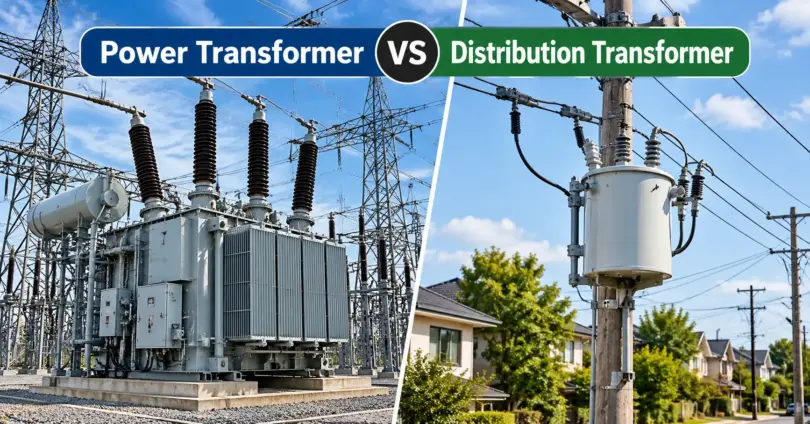

Power transformer and distribution transformer both transfer electrical energy between circuits using electromagnetic induction. The difference lies in where they sit in the grid, how they are loaded, and what their designs are optimized for. This guide covers the difference between power transformer and distribution transformer in table form, typical ratings, losses, worked efficiency examples, tap changers, and applications.
A power transformer steps voltage up or down for bulk power transfer in generation and transmission networks and usually runs close to full load. A distribution transformer steps voltage down to consumer level (for example 11 kV to 400/230 V), is installed near the load, stays energized 24/7, and is designed for low losses under changing load.
What Is a Power Transformer?
A power transformer moves large amounts of power between voltage levels in generating stations and transmission substations. Stepping voltage up (for example from 11 kV to 132 kV) lowers the current needed for the same power, which reduces resistive losses in transmission lines.
Power transformers are large, oil-filled units rated in MVA, built for long continuous service near their rated load.
What Is a Distribution Transformer?
A distribution transformer makes the final voltage reduction before electricity reaches users. For example, it can convert an 11 kV supply into a 400/230 V three-phase, four-wire supply: about 400 V between phases and 230 V between phase and neutral.
It is mounted on poles, on pads, or indoors, close to homes, shops, and factories. Its load is light at night and heavy in the evening, yet the transformer stays energized all day. This is why its design focuses on keeping no-load losses low.
Difference Between Power Transformer and Distribution Transformer
| Feature | Power Transformer | Distribution Transformer |
|---|---|---|
| Function | Bulk power transfer between voltage levels | Final supply at consumer voltage |
| Location | Generation and transmission substations | Near the load: pole, pad, or indoor |
| Voltage level | Commonly above 33 kV | Commonly 33 kV and below (11 kV, 6.6 kV) down to 400/230 V |
| Rating | Commonly above 500 kVA, expressed in MVA | Commonly up to a few MVA, expressed in kVA |
| Loading | Usually near full load | Highly variable, often well below full load on average |
| Efficiency design | Maximum efficiency near rated load | Low no-load loss, high all-day efficiency |
| Flux density | Higher, to reduce core size | Lower, to reduce core loss |
| Impedance | Higher | Lower |
| Tap changer | On-load tap changer (OLTC) is common | Off-circuit tap changer is common |
| Cooling and protection | ONAN to ONAF/OFAF; Buchholz relay and conservator on larger units | Mostly ONAN; simpler protection |
| Size and cost | Large, heavy, expensive | Compact, lower cost |
These are typical values. Classification depends on the applicable standard (IEC or IEEE) and the utility, not on size or voltage alone.
Typical Ratings and Voltages
| Type | Typical kVA / MVA range | Typical voltage classes | Common use |
|---|---|---|---|
| Pole-mounted distribution | 25 to 200 kVA | 11 kV or 6.6 kV to 400/230 V | Residential and rural feeders |
| Pad-mounted / ground-mounted distribution | 100 to 2,500 kVA | 11 kV to 400/230 V (also 33 kV primary) | Commercial areas, factories, urban networks |
| Substation power transformer | 5 to 100 MVA | 33, 66, 132, 220 kV down to 11 kV | Primary distribution and transmission substations |
| Generator step-up / grid transformer | 100 MVA and above | 220, 400, 765 kV | Power plants and grid interconnections |
Ranges are indicative. Preferred ratings and voltages differ between countries and standards.
Why higher voltage means lower current: a quick example
For a 50 MVA three-phase power transformer, the current is I = S ÷ (√3 × V):
- At 11 kV: 50,000,000 ÷ (1.732 × 11,000) ≈ 2,624 A
- At 132 kV: 50,000,000 ÷ (1.732 × 132,000) ≈ 219 A
The current is about 12 times lower at 132 kV. Because line loss is I²R, the same line has roughly 144 times less resistive loss. This is the reason for step-up transformers in transmission.
A 500 kVA distribution transformer works the same way: about 26 A on the 11 kV side and about 722 A on the 400 V side.
Design Differences Between Power and Distribution Transformers
- Core design: Power transformers use higher flux density to keep size and cost down. Distribution transformers use lower flux density and high-grade silicon steel or amorphous metal to cut core loss.
- Insulation and cooling: Larger power transformers need stronger insulation systems and forced cooling (ONAF, OFAF). Most distribution transformers rely on natural oil cooling (ONAN) or are dry-type.
- Protection: Large power transformers commonly carry a Buchholz relay, conservator, and temperature and pressure devices. Distribution units use fuses, surge arresters, and simpler protection.
- Impedance: Power transformers often have higher impedance to limit fault current. Distribution transformers have lower impedance for better voltage regulation at the consumer end.
Transformer Losses and Efficiency
Both types are highly efficient, often above 98%. What differs is which loss matters most.
Core loss (iron loss)
Caused by hysteresis and eddy currents in the magnetic core. It exists whenever the transformer is energized, even with no load, and stays roughly constant at fixed voltage and frequency.
Copper loss (winding loss)
Caused by current flowing through the winding resistance (I²R). It rises with the square of the current: doubling the current gives about four times the loss.
Condition for maximum efficiency
A transformer reaches its maximum efficiency when copper loss equals core loss. The load fraction at which this happens is:
x = √(Core loss ÷ Full-load copper loss)
Why the designs differ
A power transformer runs near rated load for long periods, so it is optimized for efficiency close to full load. A distribution transformer spends most of its life at low and medium load, so core loss dominates its wasted energy. Designers therefore use low-loss core steel and judge performance by all-day efficiency.
All-day efficiency = (Output energy in kWh ÷ Input energy in kWh over 24 hours) × 100
Worked Examples: Efficiency of a Distribution Transformer
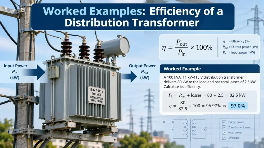
Take a 100 kVA distribution transformer with a core loss of 300 W, a full-load copper loss of 1,500 W, and a load power factor of 0.8 lagging.
Example 1: Efficiency at full load and half load
Full load: Output = 100 × 0.8 = 80 kW. Total loss = 0.3 + 1.5 = 1.8 kW. Efficiency = 80 ÷ 81.8 = 97.80%.
Half load: Output = 40 kW. Copper loss = 1.5 × (0.5)² = 0.375 kW. Total loss = 0.675 kW. Efficiency = 40 ÷ 40.675 = 98.34%.
The transformer is more efficient at half load than at full load, which is typical for distribution units.
Example 2: Load at maximum efficiency
x = √(300 ÷ 1,500) = √0.2 ≈ 0.447, so maximum efficiency occurs at about 44.7% load (≈ 44.7 kVA).
Output = 0.447 × 80 = 35.8 kW. Total loss = 0.3 + 0.3 = 0.6 kW. Maximum efficiency = 35.8 ÷ 36.4 ≈ 98.35%.
Example 3: All-day efficiency
The same transformer is energized for 24 hours with this daily load cycle (power factor 0.8):
| Duration | Load | Output (kW) | Output energy (kWh) | Copper loss (kWh) |
|---|---|---|---|---|
| 6 h | 10% | 8 | 48 | 0.09 |
| 10 h | 50% | 40 | 400 | 3.75 |
| 4 h | 100% | 80 | 320 | 6.00 |
| 4 h | 30% | 24 | 96 | 0.54 |
| Total | 864 | 10.38 |
Core loss for 24 hours = 0.3 kW × 24 h = 7.2 kWh. Total loss = 10.38 + 7.2 = 17.58 kWh. Input energy = 864 + 17.58 = 881.58 kWh.
All-day efficiency = 864 ÷ 881.58 × 100 ≈ 98.01%.
Core loss makes up about 41% of the daily loss even though the transformer was fully loaded for only 4 hours. This is why low core loss is the priority in distribution transformer design.
On-Load Tap Changer (OLTC) vs Off-Circuit Tap Changer
Tap changers adjust the turns ratio to keep output voltage within limits when supply voltage or load changes.
- OLTC: Changes taps while the transformer is energized and loaded. It is common on substation power transformers where voltage must be regulated continuously. It adds cost and maintenance.
- Off-circuit tap changer (DETC): Must be changed with the transformer de-energized. It is common on distribution transformers, where the tap is set once to suit the local supply voltage.
Applications of Power and Distribution Transformers
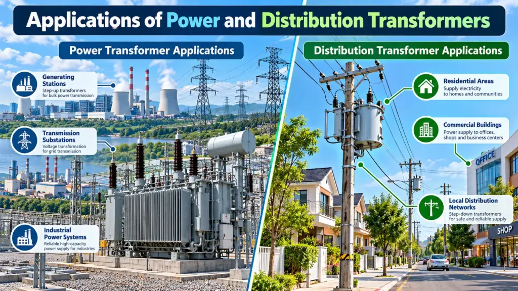
Power transformer applications
- Generator step-up at power plants
- Transmission substations and grid interconnections
- Primary distribution substations (for example 33/11 kV)
- Large industrial plants, steel mills, and railways
Distribution transformer applications
- Residential neighborhoods (pole- or pad-mounted)
- Commercial buildings, malls, and offices
- Factories and workshops needing 400/230 V supply
- Rural electrification and local feeders
Where Each Transformer Fits in the Grid
Power generation: 11 kV
↓
Step-up power transformer
↓
Transmission network: 132 kV
↓
Substation power transformer
↓
Distribution network: 11 kV
↓
Distribution transformer
↓
Homes and businesses: 400/230 V
Illustrative example. Voltage levels and number of stages vary by country and utility.
How to Choose the Right Transformer
Neither type is better in general. Pick by role: a power transformer for bulk transfer and high-voltage substations, a distribution transformer for supplying consumers at low voltage. Whichever you need, check these points:
- Voltage ratio and rated capacity (kVA or MVA)
- Expected load profile, and the cost of no-load and load losses over the transformer’s life
- Cooling method (oil or dry-type) and installation environment
- Tap changer type needed for voltage regulation
- Applicable standards and efficiency regulations, such as IEC 60076, IEEE C57.12.00, and in the EU the Ecodesign Regulation (EU) No 548/2014
Frequently Asked Questions
Can a power transformer be used as a distribution transformer?
Yes. Transformers at primary distribution substations are often power transformers. Classification depends on application, not just physical size.
Which transformer has higher efficiency?
Both can exceed 98%. Power transformers are optimized near full load, while distribution transformers are optimized for low total losses across a full day.
Why is a transformer rated in kVA and not kW?
Heating depends on voltage and current, not on the load’s power factor. The rating is therefore given in kVA (or MVA for large units).
Why do distribution transformers need low core loss?
They stay energized 24 hours a day but often run at low load, so core loss makes up a large share of their yearly energy loss, as Example 3 shows.
Is a distribution transformer always step-down?
In normal use, yes. It steps voltage down to the consumer level. Power transformers can be step-up or step-down.
Conclusion
Power transformers move bulk power at high voltage across the grid and are optimized for efficiency near full load. Distribution transformers deliver safe, usable voltage to consumers and are designed for low core loss and high all-day efficiency under changing load.
You May Also Like It:
Public Power Energy Supplier: What It Is and How It Works
Power vs Energy: What Is the Difference and Why Does It Matter?
Consumers Energy Power Outage: How to Report, Track, and Stay Safe
Xcel Power Shut Off: Everything You Need to Know About PSPS Outages