
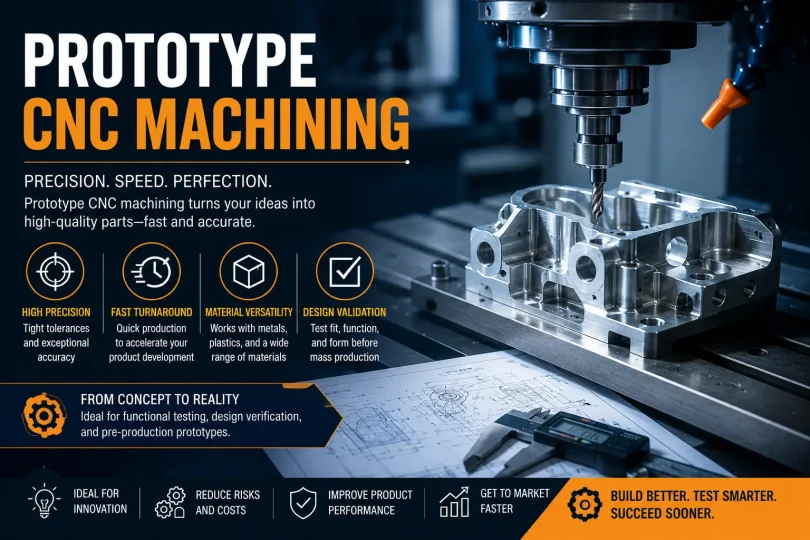

Prototype CNC machining is one of the most reliable, precise, and widely used methods in modern product development. Whether you are an engineer validating a new aerospace component, a startup testing a medical device design, or an automotive team refining a transmission part before mass production, CNC machining gives you something no other prototyping technology can match at scale: real material, real tolerances, and real functional performance in a single part before you commit to expensive tooling.
This guide goes deeper than any competitor resource. It covers not just what prototype CNC machining is, but how experienced engineers actually use it, what the real cost and tolerance numbers look like, where it beats alternatives, where it does not, and what separates a good CNC prototype from a wasted one. Every section is grounded in current industry data and real manufacturing practice.
What Is Prototype CNC Machining? A Clear, Technical Definition
Prototype CNC machining is a subtractive manufacturing process in which computer-controlled cutting tools remove material from a solid block, called a workpiece, to produce a physical part that closely mirrors the final production design. The machine follows instructions written in G-code, generated automatically from a CAD file through CAM software, and executes cuts along programmed axes with micron-level repeatability.
The word “prototype” here is critical. A prototype is the first physical version of a design, created to verify appearance, dimensions, structural integrity, and functional performance before committing to mass production processes like injection molding or die casting that require expensive tooling. A well-executed CNC prototype catches design errors early, validates manufacturing feasibility, and gives engineering teams real-world test data that digital simulations cannot fully replicate.
What separates CNC prototyping from other rapid prototyping methods is that the material you machine is the actual production material. An aluminum 6061 CNC prototype behaves exactly like an aluminum 6061 production part under load, heat, and fatigue. A 3D-printed part, regardless of how sophisticated the process, introduces layer lines, anisotropic strength, and material properties that deviate from production equivalents. For engineers who need functional test data, this distinction is not minor. It is the difference between a concept model and a real engineering validation part.
Why Engineers Choose CNC Machining for Prototyping
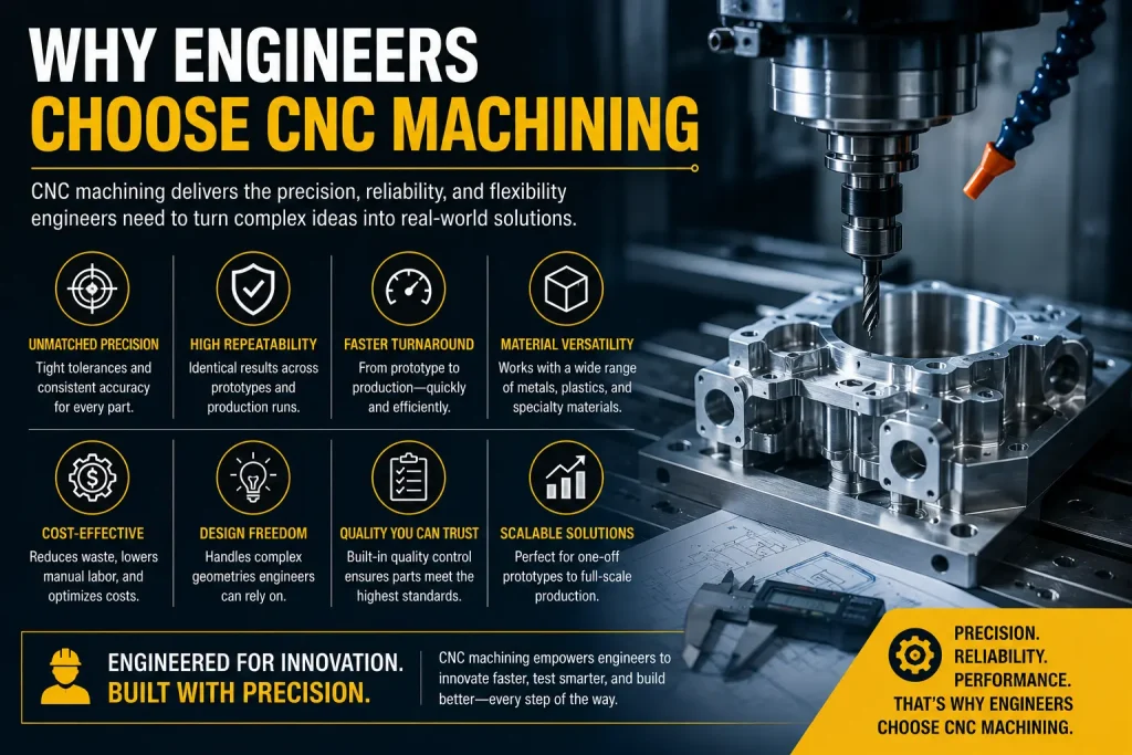
The choice to use CNC machining for prototyping over alternatives like 3D printing, urethane casting, or sheet metal forming comes down to five core advantages that are difficult to replicate by any other method at this stage of product development.
Precision That Matches Production Intent
CNC machining delivers tolerances that no additive method can consistently achieve across engineering metals and structural plastics. Standard CNC prototype tolerances sit at plus or minus 0.05 mm for general parts, tightening to plus or minus 0.01 mm for precision features in aerospace and medical applications, and reaching plus or minus 0.005 mm for ultra-critical mating surfaces in climate-controlled machining environments. By comparison, most FDM 3D printing processes achieve tolerances in the range of plus or minus 0.2 to 0.5 mm, and even high-resolution SLA processes struggle to hold plus or minus 0.1 mm reliably across all geometries.
For engineers designing assemblies with tight clearances, bearing seats, threaded interfaces, or hydraulic sealing surfaces, these numbers represent the line between a part that works and one that does not.
True Material Performance
CNC-machined prototypes are cut from wrought or extruded stock in the same alloy and temper as production parts. An aluminum 7075-T6 prototype machined from billet has the same yield strength, fatigue behavior, and thermal conductivity as the production component. This is essential for structural load testing, thermal validation, pressure testing, and regulatory qualification in industries like aerospace, medical devices, and defense.
No Tooling Investment
Unlike injection molding or die casting, CNC machining requires no hard tooling. The machine works directly from the digital CAD file. This makes it the most cost-effective method for producing one to ten units, and often for quantities up to fifty or one hundred before injection molding economics begin to favor molded production.
Speed From File to Part
A straightforward aluminum CNC prototype can move from a finalized STEP file to a finished, inspected part in two to five business days at a well-equipped shop. Complex multi-feature parts in harder materials take longer, but even these often reach the engineer within two weeks. This speed enables rapid design iteration: find a problem, revise the model, machine a new prototype, and validate again in days rather than months.
Design Flexibility Without Penalty
Because there is no tooling, each new design revision costs the same as the first. Engineers can iterate freely, changing wall thicknesses, relocating features, adjusting tolerances, and testing different geometries without carrying forward any sunk tooling cost. This freedom is particularly valuable in early development phases where the design is still evolving rapidly.
The Complete Prototype CNC Machining Process, Step by Step
Understanding the full workflow from concept to finished part helps engineers design smarter, communicate better with machining partners, and avoid the most common and costly errors that delay prototype programs.
Step 1: CAD Model Preparation and Design for Manufacturability Review
The process begins with a fully detailed 3D CAD model created in software such as SolidWorks, Autodesk Fusion 360, CATIA, or PTC Creo. The file must capture all nominal dimensions, material specification, surface finish requirements, and critical tolerances. The most common mistake at this stage is treating the CAD model as a geometric representation rather than a manufacturing instruction set.
Before the file moves to any machining shop, a Design for Manufacturability review should assess several potential issues. Wall thicknesses below 0.5 mm are prone to chatter and deflection during cutting. Internal corners have minimum radii set by the cutting tool diameter and cannot be made perfectly square without EDM operations. Deep pockets with high aspect ratios limit tool access and may require specialized long-reach tooling at higher cost. Undercut features require 4-axis or 5-axis machining setups, which add cost and lead time.
Engineers who invest thirty minutes in a DFM review before sending files to a machine shop consistently see fewer revision cycles and lower prototype costs. Many experienced CNC shops now offer DFM feedback as part of their quoting process, and this feedback should be taken seriously. A design that cannot be machined as drawn either comes back with a request for revision or, worse, gets machined in a way that approximates but does not match the design intent.
Step 2: File Submission and Quoting
A complete prototype submission package includes a 3D model in STEP or IGES format for CAM programming, a 2D drawing in PDF format that specifies all tolerances, thread specifications, surface finish requirements, material and temper, and any special processing needs such as anodizing, heat treatment, or passivation. If applicable, a bill of materials and assembly references help the shop understand fit and function context.
The quality of this documentation directly affects quote accuracy and manufacturing success. Shops that receive complete, well-documented files deliver more accurate quotes in less time, and produce parts that better match design intent. Vague specifications or missing 2D drawings often result in the shop applying default tolerances that may not suit the application, or requesting clarification that adds days to the schedule.
Step 3: CAM Programming and Toolpath Generation
Once the file package is accepted and the job is scheduled, a skilled CAM programmer imports the STEP file into software such as Mastercam, Hypermill, or Fusion 360 CAM and generates the toolpaths that the CNC machine will follow. This step is where significant engineering expertise applies. The programmer selects cutting tools based on feature geometry and material properties, sets cutting speeds and feed rates to balance material removal rate with tool life and surface finish, determines the sequence of roughing and finishing passes, and chooses workholding strategies that maintain dimensional accuracy throughout the cutting cycle.
A well-optimized CAM program reduces cycle time, improves surface finish, extends tool life, and ultimately determines whether the finished part meets its tolerance requirements. Poor toolpath programming, even on an accurate machine, produces parts with dimensional errors, poor surface texture, or excessive burring that requires additional hand finishing.
Step 4: Machine Setup and Workholding
On the shop floor, the operator mounts the raw material stock in the machine using vises, collets, custom fixtures, or vacuum tables depending on part geometry and material. Workholding quality directly affects dimensional accuracy. A part that moves or deflects during cutting will have errors that no amount of programming skill can overcome. For high-precision prototypes, operators often machine custom fixtures that support the workpiece at multiple points to minimize deflection during cutting passes.
The machine spindle, axis drives, and control system are warmed up and verified against calibration standards before precision cutting begins. Climate and thermal stability matter for the tightest tolerance work. Thermal expansion of steel at shop temperature variations can introduce errors at the ten-micron level, which is why ultra-precision machining often requires temperature-controlled environments.
Step 5: Machining, Roughing, and Finishing Passes
Actual cutting proceeds in stages. Roughing passes remove the bulk of material quickly, leaving a defined amount of stock on all surfaces. Semi-finishing passes refine geometry and improve surface condition. Finishing passes bring features to their final dimensions and surface finish targets using sharp, unworn tools at optimized cutting parameters.
For multi-sided parts, the workpiece is repositioned in multiple setups, with each setup referenced to established datums to maintain overall dimensional accuracy. Minimizing the number of setups reduces accumulated positional error and reduces cost, which is why experienced engineers design parts to be machinable in as few setups as possible.
Step 6: Inspection and Dimensional Verification
Every CNC prototype should undergo dimensional inspection against the 2D drawing before being accepted or shipped. The rigor of this inspection scales with the application and tolerance requirements. For general engineering prototypes, skilled operators use digital calipers, micrometers, depth gauges, and height gauges to verify key dimensions. For high-precision medical or aerospace parts, Coordinate Measuring Machine inspection generates formal reports that trace every critical dimension against its drawing tolerance with measurement uncertainty quantified.
First Article Inspection reports that capture all dimensions provide traceability and enable informed design decisions when dimensions fall outside specification. A well-documented FAI is an engineering asset, not just a quality formality.
Step 7: Post-Processing and Surface Finishing
Raw machined aluminum prototypes often require post-processing to meet functional or cosmetic requirements. Anodizing Type II provides corrosion protection and can be dyed to match production color specifications. Hard anodize (Type III) adds wear resistance for sliding contact surfaces. Passivation of stainless steel removes free iron from the surface to improve corrosion resistance. Bead blasting creates a uniform matte texture. Powder coating or painting matches production appearance requirements. Plating with nickel, chrome, or other metals adds hardness or conductivity.
Lead times and costs for post-processing should be factored into the prototype schedule. Anodizing adds two to five business days depending on the anodizer’s schedule and the complexity of masking required. Plating operations can take longer and often require minimum batch quantities that affect cost on single-unit prototypes.
Materials Used in Prototype CNC Machining
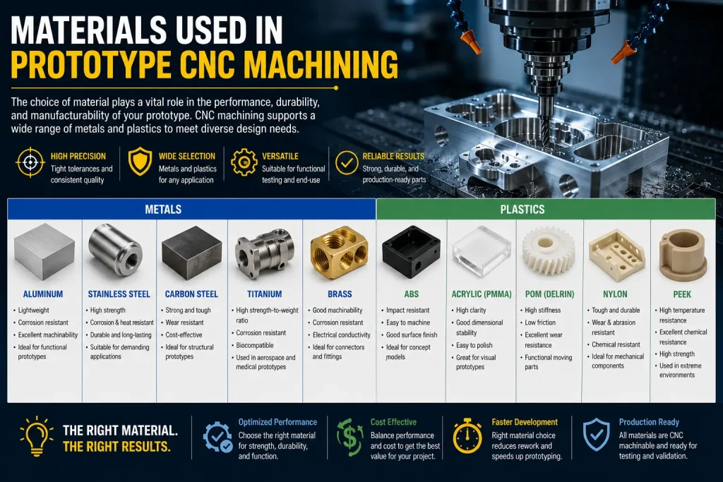
Material selection for a CNC prototype should match the intended production material wherever possible. Testing a prototype in a different material than the production part provides useful but incomplete validation data, because material properties directly affect stiffness, strength, thermal behavior, wear resistance, and manufacturing characteristics.
Aluminum Alloys
Aluminum is the most widely used CNC prototype material for good reason. It machines easily and quickly, reducing both cycle time and cost relative to harder materials. Its strength-to-weight ratio makes it valuable across aerospace, automotive, consumer electronics, and industrial equipment applications.
Aluminum 6061-T6 is the workhorse alloy for general prototype work. It offers good strength, excellent corrosion resistance, easy machinability, and is available in a wide range of stock sizes and shapes. Aluminum 7075-T6 provides significantly higher strength and is used for structural aerospace and high-performance automotive prototypes where the production intent is also 7075. The cost premium for 7075 over 6061 is modest in terms of material, but machining 7075 requires sharper tools and more care due to its tendency to chip at edges.
Stainless Steel
Stainless steel prototypes are used when the application requires corrosion resistance combined with higher strength than aluminum, or when food safety, medical biocompatibility, or high-temperature service is required. Grade 304 is the most common general-purpose stainless steel for prototyping. Grade 316 adds molybdenum for superior resistance to chloride corrosion and is the standard for marine and medical implant applications. 17-4 PH (precipitation-hardened stainless) offers high strength and hardness after heat treatment and is common in aerospace fasteners and structural components.
Stainless steel machines more slowly than aluminum and generates more heat, which requires flood coolant and higher-quality tooling. Machining time per part in stainless is typically two to four times longer than in comparable aluminum geometry, which is reflected in higher prototype costs.
Titanium
Titanium prototypes serve aerospace structural applications and medical implant validation where biocompatibility, high specific strength, and corrosion resistance are simultaneously required. Grade 5 titanium (Ti-6Al-4V) is the most common alloy in both industries. Titanium is notoriously difficult to machine. It conducts heat poorly, meaning that heat generated at the cutting edge concentrates in the tool rather than dissipating into the chip or workpiece. This leads to rapid tool wear, and titanium machining requires conservative speeds, rigid setups, and aggressive coolant delivery. Per-hour machine cost for titanium work is substantially higher than for aluminum, and cycle times are longer, making titanium prototypes among the most expensive CNC machined components by weight.
Engineering Plastics
Engineering plastics offer light weight, electrical insulation, chemical resistance, and cost advantages for certain prototype applications. Common choices include ABS for general-purpose early-stage prototypes, Nylon (PA6 and PA66) for structural and wear-resistant parts, Polycarbonate for optically clear or impact-resistant applications, PEEK for high-temperature and chemical-resistant medical or aerospace parts, Delrin (POM) for precision gears and sliding mechanisms, and PTFE (Teflon) for chemical-resistant seals and sliding contact surfaces.
Plastics present specific machining challenges. They expand and contract significantly with temperature changes during machining, which introduces dimensional variation. Many plastics contain internal stresses from the extrusion or molding process used to make the stock material, and these stresses can cause warping when material is removed. Tolerances of plus or minus 0.1 mm are typical for most engineering plastics, and achieving plus or minus 0.05 mm requires careful thermal management, stress-relief processing of the stock material, and more conservative cutting parameters.
Other Materials
Copper and brass are machined for electrical components, heat exchangers, and decorative hardware prototypes. Magnesium offers the highest specific stiffness of any common engineering metal but requires special fire suppression precautions during machining. Carbon fiber reinforced polymer (CFRP) can be CNC machined but requires diamond-coated tooling to manage abrasive wear, and generates fine particulate dust that requires proper extraction and respiratory protection.
CNC Machining Methods Used in Prototyping
Not all CNC machining is the same. Different machine types and configurations suit different prototype geometries, feature types, and accuracy requirements.
CNC Milling
Milling uses rotating multi-flute cutting tools that move across a stationary or slowly feeding workpiece. It is the most versatile CNC process and handles flat surfaces, pockets, slots, external profiles, holes, and complex 3D contoured surfaces. Three-axis milling machines move in X, Y, and Z, which is sufficient for most prismatic parts and moderately complex geometries. Four-axis machines add a rotational axis, typically allowing the part to be indexed to machine features on multiple faces without manual repositioning. Five-axis machining adds two rotational axes, enabling the cutting tool to approach the workpiece from virtually any angle in a single setup. This capability is essential for complex aerospace structures, turbine blades, medical implants, and any part where features on multiple faces must be machined in tight positional relationship to each other.
Five-axis machining reduces the number of setups required for complex parts, which improves dimensional accuracy by eliminating accumulated repositioning error, and reduces lead time by consolidating operations that would otherwise require multiple machine configurations.
CNC Turning
Turning rotates the workpiece on a spindle while a single-point cutting tool moves along the axis of rotation to remove material. It produces cylindrical geometries including shafts, rods, rings, threaded fasteners, and bores with exceptional roundness and concentricity. CNC turning centers with live tooling add driven milling and drilling tools that can machine non-rotational features like flats, keyways, and radial holes without removing the part from the machine. This combined turning and milling in one setup is particularly valuable for complex rotational parts like valve bodies, hydraulic fittings, and precision spindles.
Electrical Discharge Machining
EDM uses electrical sparks to erode material from an electrically conductive workpiece. It does not exert cutting forces on the part, making it valuable for extremely thin-walled features, sharp internal corners that cannot be reached by rotating tools, deep narrow slots, and hardened materials that are difficult to machine conventionally. Wire EDM cuts profiles through a workpiece using a continuously fed thin wire as the electrode. Sinker EDM uses a shaped electrode to create complex cavity geometries commonly used in mold making.
EDM processes are slower than conventional CNC milling, but they are the only practical option for certain geometries and hard materials. For prototype work, EDM is often used in combination with conventional machining to create features that cannot be produced by rotary tools alone.
Multi-Axis Machining Centers
Modern machining centers combine milling, turning, and sometimes grinding operations in a single machine platform with multiple tool magazines and automated part handling. For complex prototypes that would traditionally require several separate machine setups, multi-axis machining centers reduce lead time, improve accuracy by keeping the part fixtured throughout all operations, and lower cost by reducing non-cutting setup time. These machines represent the leading edge of prototype machining capability and are particularly valuable for high-complexity aerospace and medical device prototypes.
Tolerances in Prototype CNC Machining: What the Real Numbers Mean
Tolerance specification is one of the most consequential and frequently misunderstood aspects of prototype CNC machining. Tolerances define how much a machined dimension is allowed to deviate from the nominal drawing dimension. Tighter tolerances increase manufacturing difficulty, machining time, inspection requirements, and cost.
Standard Tolerance Ranges by Application
For general engineering prototypes where functional requirements do not demand extreme precision, plus or minus 0.1 mm represents a comfortable working tolerance that most competent CNC shops can achieve consistently without special processes. This is the default tolerance recommended by ISO 2768 medium class (m) for features in the 30 to 120 mm dimensional range.
For mechanical assemblies with clearance fits, bearing interfaces, and hydraulic components, tolerances of plus or minus 0.05 mm are typically required and achievable on well-maintained CNC equipment with proper fixturing and toolpath strategies. This is the range most commonly encountered in automotive and industrial prototype work.
For aerospace structural joints, medical implants, precision optics mounts, and other applications where dimensional deviation has safety or performance consequences, tolerances of plus or minus 0.01 mm are specified on critical features. Achieving these tolerances consistently requires higher-grade machine tools, climate-controlled environments, careful thermal management during cutting, and 100 percent dimensional inspection on every part.
Ultra-precision features at plus or minus 0.005 mm and tighter require specialized grinding operations, air-bearing spindles, and measurement in temperature and humidity-controlled metrology rooms. These tolerances are expensive to achieve and should be reserved for the specific features where they are genuinely required by function or assembly, not applied uniformly across the entire part.
The Cost Relationship with Tolerance
The relationship between tolerance and cost is not linear. Moving from plus or minus 0.1 mm to plus or minus 0.05 mm roughly doubles machining and inspection time for affected features. Moving to plus or minus 0.01 mm can increase cost four to six times for those features. Ultra-tight tolerances approaching plus or minus 0.001 mm can add a cost premium of twenty to forty times compared to standard work.
A practical rule for prototype cost management is to identify which dimensions are truly critical to function, safety, or assembly, and specify tight tolerances only on those dimensions. For everything else, default tolerances per ISO 2768-m are appropriate and will be interpreted as such by any competent shop. Over-specifying tolerances is one of the most common and avoidable causes of inflated prototype costs, longer lead times, and unnecessary manufacturing complexity.
ISO 2768 and GD&T
ISO 2768 is the international standard for general tolerances in CNC machining, defining acceptable variation for features whose individual tolerances are not otherwise specified on the drawing. Specifying ISO 2768 medium class (m) on a drawing’s title block communicates a complete set of tolerance expectations for all unspecified dimensions without requiring individual callouts on every feature.
Geometric Dimensioning and Tolerancing per ASME Y14.5 provides a more complete language for controlling not just size but form, orientation, location, and runout of machined features. GD&T is particularly valuable for controlling flatness of machined datum surfaces, perpendicularity of bores to mounting faces, concentricity of rotational features, and true position of hole patterns. Engineers who invest in learning GD&T and applying it appropriately on prototype drawings achieve better first-article results and have more productive conversations with machine shop quality teams.
Cost of Prototype CNC Machining: Real Numbers and What Drives Them
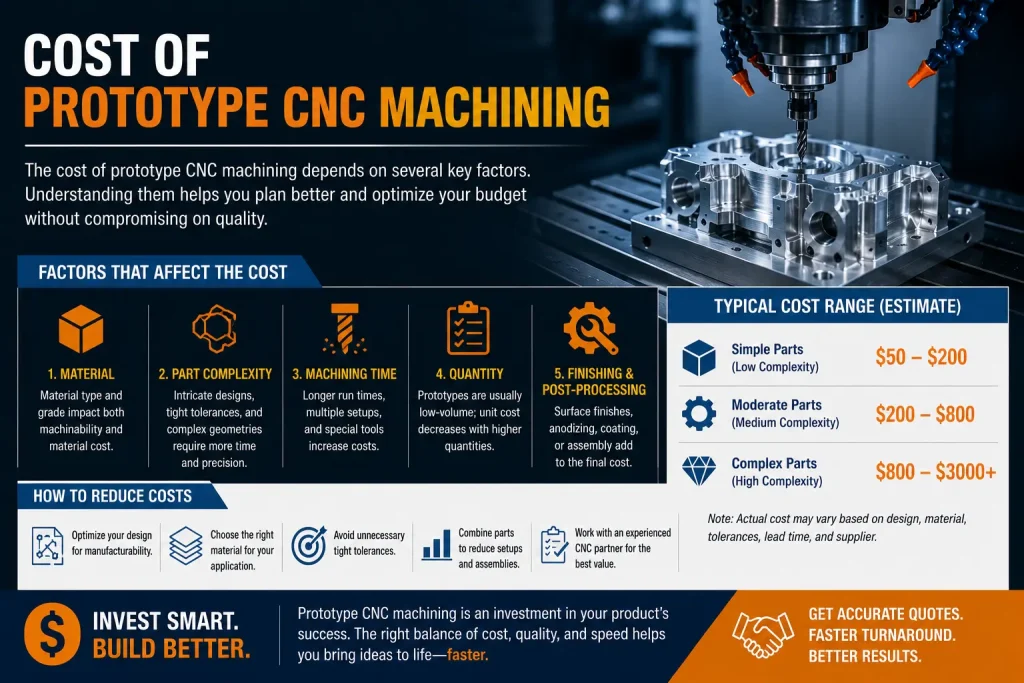
Understanding what drives CNC prototype costs allows engineers and project managers to make smarter design and procurement decisions. The range of prototype costs is genuinely wide. A simple aluminum bracket machined in a single setup might cost one hundred dollars at a competitive shop. A complex titanium medical component requiring five-axis machining, tight tolerances, and formal CMM inspection might cost fifteen hundred dollars or more for a single unit.
Primary Cost Drivers
Material cost is typically the largest single line item on a CNC prototype quote, accounting for thirty to fifty percent of total cost for metal parts. Aluminum is inexpensive. Stainless steel costs roughly three to five times more per kilogram than aluminum and machines more slowly. Titanium costs eight to fifteen times more than aluminum per kilogram and requires slower cutting speeds and more aggressive tooling, which compounds the material cost premium substantially.
Machine time is the second largest cost factor. Machining time is determined by part complexity, number of setups, total material volume removed, required tolerances, and material machinability. A part that can be machined in one setup in thirty minutes costs fundamentally less than an equally sized part requiring three setups and two hours of cutting time, even at the same material cost.
CAM programming is a fixed cost that does not scale with quantity. For a one-off prototype, programming can represent sixty to seventy percent of total job cost. For a batch of fifty identical parts, that same programming cost is diluted to a few percent per unit. This is the fundamental reason CNC cost per unit drops dramatically with quantity, and why prototype pricing for single units appears high relative to production pricing.
Post-processing adds cost and lead time. Anodizing Type II for a small aluminum part typically adds fifty cents to two dollars per part for large quantities, but minimum lot charges at anodizing shops mean that a single prototype anodize can cost fifty to one hundred fifty dollars for setup alone. Engineers who plan post-processing requirements early and batch finishing operations across multiple prototype iterations reduce these overhead costs significantly.
Typical Cost Ranges by Part Type
Simple prismatic aluminum parts in a single setup range from one hundred to three hundred dollars for a single prototype at a competitive shop. Moderately complex aluminum parts requiring two or three setups range from three hundred to eight hundred dollars. Complex aluminum parts with five-axis requirements, tight tolerances, or extensive post-processing range from eight hundred to two thousand dollars. Steel and titanium parts at equivalent complexity cost two to four times the aluminum pricing due to material and machine time premiums.
These are single-unit prices. Ordering five to ten identical prototypes typically reduces per-unit cost by twenty to forty percent due to setup amortization and programming reuse.
Lead Times for Prototype CNC Machining
Lead time expectations should be set realistically based on part complexity, material availability, and shop capacity rather than on optimistic assumptions.
Standard aluminum prototypes with readily available material and no special processing typically require three to seven business days from drawing approval to ship. Complex parts requiring five-axis machining, specialty materials with longer procurement lead times, or tight tolerances requiring additional inspection steps typically require two to three weeks. Aerospace or medical parts requiring formal first article inspection reports, material certifications, and traceability documentation often require four to six weeks due to the administrative and quality requirements in addition to machining time.
Rush or expedited prototypes are available at most shops for a premium, typically forty to one hundred percent above standard pricing. For critical development milestones, the cost of a rush fee is almost always justified compared to the cost of a delayed product launch decision or missed testing window.
Prototype CNC Machining Versus Other Prototyping Technologies
Choosing the right prototyping method requires understanding what each technology does well and where it falls short. CNC machining is not always the best choice, and the most capable product development teams use multiple methods strategically across different phases of development.
CNC Machining Versus FDM 3D Printing
FDM 3D printing is faster and cheaper for very early concept models where visual form and rough dimensional approximation are the only requirements. It allows exploring multiple design variations simultaneously at low cost. However, FDM parts have layer-line anisotropy, dimensional tolerances an order of magnitude worse than CNC machining, and material properties that do not match production metals or engineering plastics accurately. FDM is not appropriate for functional mechanical testing, load bearing evaluation, sealing surface validation, or any test where material properties matter.
CNC machining costs more and takes slightly longer than FDM for simple geometries, but it produces parts that can be functionally tested with confidence, that meet drawing tolerances, and that use actual production materials. The choice is straightforward: use FDM for geometry visualization, use CNC machining for functional validation.
CNC Machining Versus SLA and SLS 3D Printing
SLA and SLS produce better surface finish and dimensional accuracy than FDM, but still cannot match CNC machining for metal parts in terms of material properties, tolerance capability, or surface integrity. SLS nylon parts are useful for functional plastic testing in non-structural applications. SLA resin parts are brittle and UV-sensitive, limiting their useful life for functional testing.
For plastic prototypes, the choice between SLS and CNC machined plastic depends on geometry complexity, required material properties, and quantity. SLS handles thin walls and complex internal geometries more easily than CNC machining. CNC machined plastic parts have better surface finish, tighter tolerances, and material properties that match the production plastic more closely.
CNC Machining Versus Investment Casting for Metal Prototypes
Investment casting can produce complex near-net-shape metal prototypes that would require extensive multi-axis machining if machined from solid. However, casting prototypes require pattern tooling that costs thousands to tens of thousands of dollars and takes weeks to produce. Mechanical properties of cast metal differ from wrought billet, and internal porosity can complicate structural testing.
CNC machined prototypes from billet have superior material properties and require no tooling investment, making them the default choice for low quantities. Investment casting becomes economical when prototype quantities reach twenty to fifty units and when the part geometry cannot be practically machined from solid billet.
CNC Machining Versus Injection Molding for Plastic Prototypes
Injection molding tooling for plastic prototypes requires mold investment ranging from five thousand to over one hundred thousand dollars depending on complexity, and lead times of four to twelve weeks for the mold. CNC machined plastic prototypes require no tooling, cost a few hundred dollars per part, and can be in hand within a week.
The practical strategy in most product development programs is to validate design intent with CNC machined plastic prototypes through several design iterations, then commit to injection mold tooling once the design is stable and proven.
Industry Applications of Prototype CNC Machining
Prototype CNC machining is a cross-industry technology, but its application characteristics vary by sector in ways that reflect each industry’s requirements for precision, material, regulatory compliance, and development speed.
Aerospace and Defense
Aerospace prototype requirements are defined by the combination of extreme precision, structural performance requirements, and regulatory traceability. Structural brackets, housings, fittings, and actuator components are prototyped in aluminum, titanium, and high-strength steel alloys. Tolerances are typically tight, material certifications and traceability to raw material heat lot are required, and formal first article inspection reports are standard. Five-axis machining is common due to the organic geometry of many aerospace structures. Development timelines are long but uncompromising on quality, making the cost premium for precision CNC prototyping consistently justified.
Medical Devices
Medical device prototyping under FDA regulatory frameworks requires documentation, material biocompatibility certification, and manufacturing process traceability that goes well beyond typical commercial prototype practice. Surgical instruments, orthopedic implants, diagnostic equipment housings, and fluid handling components are frequently prototyped in stainless steel 316L, titanium Grade 5, and PEEK. Dimensional accuracy is critical because medical devices must fit anatomical constraints and interface with surgical tools with defined precision. CNC machining is the dominant prototyping method in this sector because it can meet both the dimensional and material property requirements simultaneously.
Automotive
Automotive prototype programs use CNC machining across a wide range of components from engine and transmission parts to suspension components, brake systems, and body structure brackets. Aluminum alloys dominate for mass-sensitive applications. Steel and cast iron alloys are used for high-load structural and powertrain components. Development cycles in automotive are intensive, with tight schedules and multiple iteration rounds. Lead time and cost competitiveness matter, and many automotive OEMs maintain in-house CNC prototype shops capable of very rapid turnaround on critical path components.
Consumer Electronics
Consumer electronics prototyping uses CNC machining primarily for structural aluminum housings, heat sinks, connector shells, and precision mechanical assemblies. Aluminum 6061 and 7075 are standard materials. Surface finish quality is critical because consumer electronics prototypes are used for appearance validation as well as functional testing, and anodized aluminum surface quality directly affects the perceived premium of the final product. CNC machining in this sector is characterized by high precision, excellent surface finish requirements, and very rapid iteration cycles driven by compressed product development timelines.
Industrial Equipment
Industrial prototypes span a wide range of sizes and complexity levels, from small precision valve bodies and pump housings to large structural frames and gearbox casings. Material selection is application-driven, covering steels, cast irons, bronzes, and engineering plastics depending on the function. CNC machining is used throughout the development process, and many industrial equipment manufacturers maintain in-house machining capability to support rapid prototype and pre-production builds.
How to Select the Right CNC Prototyping Partner
The quality of a CNC prototype is only as good as the shop that makes it. Choosing a machining partner is a consequential decision that affects prototype quality, schedule reliability, and ultimately the speed and confidence of your product development process.
Relevant certifications tell you that a shop has documented quality systems and has been audited against defined standards. ISO 9001 indicates a general quality management system. AS9100D is the aerospace quality standard. ISO 13485 covers medical device manufacturing. IATF 16949 applies to automotive supply chain quality. These certifications are not guarantees of quality, but their absence for work in regulated industries should be a disqualifying factor.
Machine capability matters. A shop equipped with modern 5-axis machining centers, climate-controlled environments for precision work, and a CMM inspection room is capable of producing parts that a shop with older 3-axis equipment and manual inspection cannot. Ask specifically about machine vintages, axis configurations, and metrology capabilities when evaluating a new shop.
Communication quality is a leading indicator of execution quality. A shop that responds to RFQs promptly, provides DFM feedback before quoting rather than after encountering problems during machining, and keeps customers informed of schedule status is a shop that treats manufacturing as an engineering partnership rather than a transaction.
First article pass rate is an industry benchmark for shop quality. A first article inspection pass rate above 95 percent indicates that parts typically come out right the first time, which means fewer delays, revisions, and cost overruns. Pass rates below 85 percent indicate systemic quality problems that flow back to the customer as delays and increased costs.
Common Mistakes That Make CNC Prototypes Fail or Cost Too Much
Years of prototype program experience reveals recurring patterns in the mistakes that delay programs, inflate costs, and produce parts that do not meet requirements. Understanding these failure modes allows engineers to avoid them systematically.
Specifying unnecessarily tight tolerances is the single most avoidable source of inflated prototype costs. Industry analysis consistently finds that over-specification of tolerances accounts for twenty-five to forty percent of unnecessary manufacturing costs in prototype development. Before calling out any tolerance tighter than plus or minus 0.05 mm, ask whether the specific function, assembly, or safety requirement actually requires that precision. If the answer is not clearly yes, use the ISO 2768-m default.
Ignoring DFM during design is the next most common and costly mistake. Features that are difficult to machine, such as very deep narrow pockets, extremely thin unsupported walls, or internal corners requiring square profiles, may be geometrically possible to design but impractical or impossible to machine reliably. A thirty-minute DFM conversation with a machining expert before finalizing the design can save weeks of redesign and reprototyping after the first parts come back with problems.
Submitting incomplete drawing packages creates ambiguity that either results in incorrect parts or delays while the shop seeks clarification. A complete package with a STEP file and a fully dimensioned and toleranced 2D drawing with material specification, surface finish requirements, and post-processing notes eliminates ambiguity and enables accurate quoting and efficient machining.
Underestimating material costs for high-performance alloys leads to budget surprises and schedule pressure. Titanium, Inconel, and other high-performance alloys cost significantly more than the commonly used aluminum alloys both in raw material and in machining time. Budget these materials realistically from the beginning of the prototype program.
Requesting single-unit prototypes when multiple design iterations are likely adds unnecessary setup cost to each iteration. When a design is still evolving and multiple iterations are expected, ordering two or three units per iteration amortizes setup and programming costs, provides spares for parallel testing, and often costs less total than ordering one unit per iteration.
Quality Assurance and Inspection Methods for CNC Prototypes
Quality assurance in CNC prototyping is not an afterthought applied after machining. It begins at the DFM review stage and continues through material verification, in-process monitoring, and final dimensional inspection.
Material verification confirms that the raw stock used to machine the prototype is the correct alloy and temper. For regulated applications in aerospace and medical devices, this verification requires material test reports or mill certifications that trace the material to a specific heat or lot with documented chemistry and mechanical properties. Receiving a machined part only to discover it was made from a lower-grade alloy than specified is a problem that material certification requirements exist to prevent.
In-process dimensional checks allow operators to verify critical dimensions while the part is still on the machine, enabling correction of any drift before it becomes a scrap event. Many modern CNC machining centers have on-machine probing systems that automatically measure features between operations and adjust cutting parameters to compensate for any dimensional deviation from target.
Final inspection using Coordinate Measuring Machines provides the most rigorous and documentable dimensional verification available. CMM inspection generates formal reports that capture measured values for every critical dimension alongside drawing nominal values and tolerances, with pass or fail status clearly indicated. These reports provide engineering teams with the quantitative data needed to make informed decisions about whether a prototype meets requirements or needs revision.
The Future of Prototype CNC Machining: Trends Shaping the Industry in 2025 and Beyond
The prototype CNC machining industry is evolving rapidly in response to technology developments, changing customer requirements, and broader manufacturing market forces.
Five-axis machining adoption continues to accelerate. Industry data indicates that five-axis machining center installations have grown by over twenty percent since 2021, driven by demand for complex prototype geometries that cannot be efficiently produced on three-axis equipment. As five-axis machine prices continue to decline relative to capabilities, this technology is becoming accessible to a broader range of shops, improving competitive pricing for complex prototype work.
Digital manufacturing integration is compressing lead times across the industry. Shops that offer instant AI-powered quoting, automated DFM feedback, and real-time order tracking give engineering teams faster design-to-decision cycles. The best-in-class shops now offer DFM feedback and accurate quotes within hours of file submission, compared to the multi-day quoting cycles that were standard just a few years ago.
Hybrid manufacturing combining CNC machining with metal additive manufacturing is expanding the range of geometries achievable in a single prototype program. Near-net-shape metal AM parts that would require excessive machining stock removal if machined from billet can be built additively and then finish-machined to final tolerances, combining the geometric freedom of additive manufacturing with the dimensional precision and surface quality of CNC machining.
Automation in prototype machining, including robotic workpiece loading, automated tool measurement and breakage detection, and lights-out machining of simpler prototype features, is gradually improving throughput and consistency in prototype shops. These improvements benefit prototype customers through better schedule reliability and more consistent part quality.
Key Takeaways for Engineers and Product Teams
Prototype CNC machining is the most reliable path from digital design to functional, testable physical part in production material at production tolerances. No other prototyping technology matches it for the combination of material authenticity, dimensional precision, and broad geometric capability that functional engineering validation requires.
The engineers who get the most value from CNC prototyping are those who design with manufacturability in mind from the beginning, specify tolerances based on functional requirements rather than conservative habit, prepare complete and unambiguous documentation packages, work collaboratively with their machine shop partners, and treat prototype results as engineering data rather than pass-fail decisions.
The global CNC machining market reflects how central this technology is to modern manufacturing. Valued at approximately 68.7 billion dollars in 2023 and projected to reach 116.7 billion dollars by 2032, the industry’s growth is driven by increasing demand for precision across aerospace, automotive, medical devices, and electronics sectors. Prototype machining sits at the highest-value end of this market, where engineering expertise, machine capability, and quality systems combine to produce the parts that define the next generation of products across every industry.
Understanding prototype CNC machining deeply, from the physics of the cutting process to the economics of tolerance specification to the practical realities of shop selection and file preparation, is a genuine competitive advantage for engineering teams building complex products on tight development timelines.
You May Also Like It:
CNC Machining Tolerances: The Complete Expert Guide
MIG vs TIG Welding: Complete Guide to Differences and Procedures




[…] Prototype CNC Machining: The Complete Expert Guide […]
[…] & Engineering: Concepts, CAD models, prototypes and validation define what will be […]