
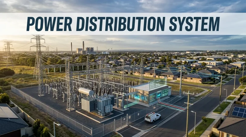

A power distribution system is the complete electrical network that takes high-voltage utility supply and routes it, at safe, usable voltage levels, through switchgear, transformers, panelboards, and conductors to every load in a building. Its core function is to step down voltage, divide load into protected circuits, and stop faults before they damage equipment or injure people.
Understanding this system matters beyond the textbook. Poor design decisions cause fires, failed inspections, and six-figure equipment losses. This guide covers the architecture, the real failure modes, the NEC rules that inspectors actually cite, and the sizing questions that separate a well-built system from one that needs a costly rebuild in five years.
The Real Anatomy of a Power Distribution System
A power distribution system moves electricity through six distinct stages, each with a specific protective and operational role.
The utility service entrance is where the utility’s medium-voltage feed, typically between 4.16kV and 34.5kV, crosses the property line. The main switchgear immediately downstream is the first point where power is metered, protected by overcurrent devices, and split into separate distribution paths. Step-down transformers then reduce voltage to levels usable by building loads: 480V for motors and large HVAC equipment, 208V/120V for lighting and receptacles.
Distribution panels and switchboards divide load into circuit groups and route power to panelboards, which are the final split point before branch circuits feed outlets, fixtures, and equipment directly. The grounding and bonding system ties all metal enclosures to earth, giving fault current a low-impedance path that trips protective devices instead of energizing surfaces people can touch.
One critical detail most guides omit: transformers act as harmonic filters, not just voltage converters. Non-linear loads such as variable frequency drives (VFDs), LED drivers, and server power supplies inject harmonic currents that overheat transformer windings. An undersized or standard-rated transformer under heavy non-linear load can fail years before its nameplate life, strictly because harmonic loading was never factored into the original design.
Power Distribution System vs. Power Distribution Unit: A Necessary Distinction
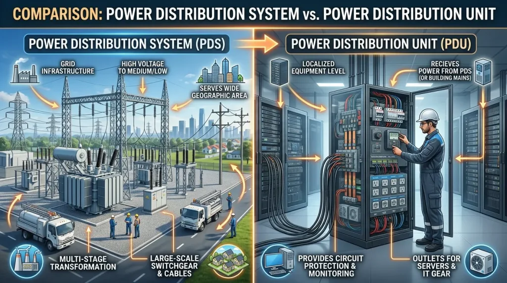
A power distribution system (PDS) refers to the entire electrical infrastructure of a building or facility, from service entrance to final branch circuit. A power distribution unit (PDU) is a single piece of equipment, typically rack-mounted, that distributes power within a localized footprint such as a server rack or temporary event setup.
The distinction matters in practice. When a data center technician says “check the PDU,” they mean the rack-level device, not the building’s electrical backbone. Confusing the two leads to misdiagnosed problems and incorrect equipment specifications on projects.
Radial, Ring, and Redundant Topologies: What Each One Actually Provides
The three core distribution topologies differ in fault tolerance, cost, and appropriate application, and choosing the wrong one for a facility’s criticality level is one of the most expensive design mistakes in electrical engineering.
Radial distribution routes power in a single path from source to load. It is the lowest-cost topology to install and the simplest to troubleshoot, but a single upstream fault de-energizes everything downstream of it. Radial systems are appropriate for small retail, light commercial, and residential applications where brief outages are acceptable.
Ring distribution loops the feeder back to its source, so that a fault anywhere in the loop can be isolated while power continues reaching every load from the other direction. The upfront cost is higher due to additional conductors and switching equipment, but ring topology is standard for office buildings, schools, and mid-size facilities where unplanned outages carry measurable business cost.
N+1 redundant systems provide one additional unit of capacity beyond the load requirement. If one component fails, the spare absorbs the load with no interruption. 2N redundant systems are fully mirrored, with two independent power paths serving every load simultaneously. Data centers and life-safety systems use 2N because a single unplanned outage can cost six figures per hour, making the capital cost of full redundancy mathematically justified.
| Topology | Upfront Cost | Fault Tolerance | Best Fit |
|---|---|---|---|
| Radial | Low | None (single point of failure) | Small retail, residential |
| Ring | Medium | Moderate (isolates single faults) | Office buildings, schools |
| N+1 Redundant | High | High (one failure absorbed) | Data centers, hospitals |
| 2N Redundant | Very High | Maximum (full mirrored backup) | Tier IV data centers, life-safety systems |
Where Power Distribution Systems Actually Fail in the Field
Power distribution systems fail in the field due to thermal degradation, mechanical loosening, overloading, and grounding system deterioration. The primary breakdown points are predictable and detectable before they cause failures, which is why most field failures represent a maintenance gap rather than an equipment defect.
Loose lug connections are the most common failure mode in commercial and industrial systems. Thermal cycling from daily load fluctuations gradually loosens bolted terminations at breakers, bus bars, and lugs. The result is elevated contact resistance, which produces heat detectable by infrared thermal scanning before it ever trips a breaker or causes an arc flash event. Annual IR scans on all major terminations catch this at the maintenance stage, not the incident stage.
Neutral conductor overloading is a failure mode specific to buildings with heavy non-linear loads. In facilities with dense populations of computers, LED lighting, and variable-speed drives, neutral conductors can carry more current than the phase conductors they serve. This occurs because third-harmonic currents from non-linear loads add on the neutral rather than cancel, a phenomenon that NEC Article 310 addresses through derating rules that older designs frequently ignored.
Conduit fill violations from phased additions are common in tenant improvement projects. Additional circuits pulled into existing conduit during renovations frequently push fill percentages beyond NEC Table C limits. The system operates within tolerance in mild conditions but fails thermally during summer heat waves when ambient temperature reduces the conductor’s available ampacity.
Grounding electrode degradation removes the fault current path that makes the entire protective system work. Ground rods corrode over years in moist or acidic soil. Bonding jumpers removed during renovations and never reinstalled leave metal enclosures with no path to ground. Neither condition is visible without testing, and both create shock hazards that appear only when a fault occurs.
NEC Compliance: What Inspectors Actually Cite on Commercial Projects
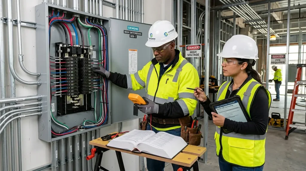
NEC compliance in power distribution systems is enforced at inspection, and the citations that delay or fail projects cluster around four consistent areas.
NEC Article 240 governs overcurrent protection sizing. The most common citation is a breaker rated below the conductor’s ampacity, which means the conductor can carry more current than the breaker will interrupt, leaving the wire unprotected against overload. Inspectors flag this consistently on projects where circuit sizing was handled informally.
NEC Article 250 covers grounding and bonding. Missing bonding jumpers on metal raceways is the most frequently cited violation, followed by improper grounding electrode conductor sizing and missing equipment grounding conductors in retrofit work.
NFPA 70E is not part of the NEC but governs arc flash hazard labeling and PPE selection. Most jurisdictions require equipment to carry current arc flash labels before final sign-off. Labels become inaccurate after any change in upstream transformer size, added generation, or significant load reconfiguration, and outdated labels are a real liability exposure in the event of an incident.
NEC 700.27 selective coordination requires that overcurrent devices in emergency systems be configured so the device closest to a fault trips first. A branch-level fault must not de-energize the main emergency panel. Achieving selective coordination requires careful review of breaker time-current curves during design, not after installation.
How to Size a Power Distribution System Correctly
Correct sizing of a power distribution system depends on five inputs that must be established before any equipment is specified.
Connected load and growth projection determine the minimum service capacity required today and the headroom needed for the next 10 years. Designing only to current load without growth margin forces a service upgrade, which requires full utility coordination and typically costs far more than building in headroom from the start.
Diversity factor reflects the reality that not all connected loads operate at full capacity simultaneously. Applying an appropriate diversity factor, typically 0.6 to 0.9 depending on building type and occupancy, prevents oversizing that wastes capital on larger-than-necessary transformers and switchgear.
Harmonic load percentage determines whether standard transformers are adequate or whether K-rated transformers and derated neutral conductors are required. When non-linear loads exceed roughly 20-25% of total connected load, harmonic distortion is significant enough to affect transformer sizing and neutral conductor selection.
Acceptable downtime tolerance determines topology selection. A building where a two-hour outage is a minor inconvenience and a building where a two-hour outage costs $500,000 are not candidates for the same distribution architecture.
Future EV charging and on-site generation load is the most consistently overlooked sizing input in current projects. EV charging infrastructure and rooftop solar installations are pushing commercial buildings past their original service capacity at a rate no standard design allowance anticipated. The cost to add service capacity headroom during initial design is a fraction of the cost to perform a service upgrade after occupancy, which requires utility coordination, permitting, and often partial building shutdown.
Where Smart Power Distribution Is Heading
Smart power distribution systems add real-time monitoring, DC distribution, and integrated storage to the traditional protection and routing functions of a conventional system.
Panel-level power monitoring gives facility operators visibility into load by circuit, shift, or tenant in real time. The practical value is demand charge management: knowing which loads are driving peak demand allows operators to shift or shed load before the peak is recorded by the utility meter, reducing the demand charge component of the electricity bill directly.
DC microgrids are gaining adoption in data centers and facilities with significant on-site solar generation. Every AC-to-DC and DC-to-AC conversion in a conventional system loses 2-5% of energy. A DC microgrid that keeps power in DC form from the solar array through the server power supply eliminates multiple conversion stages and measurably reduces facility energy consumption.
Automatic transfer switches integrated with battery storage are changing how backup power operates. Rather than sitting idle, battery systems paired with smart transfer switches actively shift loads between the grid and stored power based on time-of-use utility pricing, reducing peak demand charges while maintaining full backup capability.
Maintenance That Actually Extends System Life
Extending the service life of a power distribution system requires scheduled testing, not reactive repair. The systems that fail prematurely almost always share one characteristic: maintenance was deferred until a failure forced it.
- Perform infrared thermal scans on all major connections and terminations annually. Increase scanning frequency to semi-annual in high-vibration industrial environments where connections loosen faster.
- Torque-check bolted connections during every scheduled shutdown. Thermal cycling loosens connections between maintenance intervals, and factory torque values do not hold indefinitely.
- Test ground resistance every one to three years. Testing frequency should reflect soil conditions: moist, acidic, or sandy soils corrode ground rods faster than stable clay or rock environments.
- Update arc flash studies after any change in upstream transformer rating, added generation capacity, or significant load reconfiguration. Calendar-scheduled updates are insufficient because a major load change can alter arc flash incident energy levels immediately.
- Keep as-built single-line diagrams current. Outdated documentation extends fault isolation time during outages more often than the fault itself does.
Frequently Asked Questions
What is the difference between a distribution panel and a switchboard in a power distribution system?
A switchboard is a large, front-accessible assembly used at or near the service entrance to distribute power to major load centers throughout a facility. A panelboard is smaller, installed closer to the loads it serves, and feeds individual branch circuits such as lighting and receptacle circuits within a single floor or area.
How does load diversity factor change the equipment specifications in a power distribution system?
Diversity factor accounts for the statistical reality that not all connected loads draw full current simultaneously. Applying a diversity factor of 0.7, for example, means the distribution equipment is sized for 70% of the total connected load. Without this adjustment, systems are significantly oversized, which increases both equipment cost and energy losses at partial load.
When does a power distribution system require K-rated transformers instead of standard ones?
K-rated transformers are required when the load includes a significant proportion of non-linear devices, generally when VFDs, switching power supplies, or LED drivers represent more than 20-25% of total load. Standard transformers overheat under harmonic currents because their windings were not designed for the additional eddy current losses that non-linear loads produce.
How do you confirm that a step-down transformer in a distribution system is being overloaded?
The most reliable field method is infrared thermography. A transformer operating consistently above its rated temperature rise, measured at the core and windings, is being overloaded. A secondary indicator is elevated total harmonic distortion (THD) on the secondary side, measurable with a power quality analyzer, which confirms that harmonic loading is the overload cause.
What is selective coordination and why is it required in emergency power distribution systems?
Selective coordination means configuring overcurrent protective devices so that only the device immediately upstream of a fault operates, leaving all other circuits energized. NEC 700.27 requires selective coordination in emergency systems because a branch-circuit fault must not de-energize the entire emergency panel. Achieving it requires matching breaker time-current curves during the design phase, not after the system is installed.
Can branch circuits be added to an existing panelboard without a service upgrade?
Branch circuits can be added to an existing panelboard when spare breaker slots are available and the additional load does not exceed the panelboard’s rated ampacity or the feeder’s capacity. If the panel is fully loaded or the feeder is near its rated limit, options are a downstream subpanel fed from a new circuit or a full service entrance upgrade, which requires utility involvement.
What triggers the need for a new arc flash study on an existing power distribution system?
A new arc flash study is required after any change that alters fault current magnitude or duration: utility transformer replacement, addition of on-site generation, significant load additions, or any change in upstream overcurrent device ratings or settings. Existing arc flash labels become inaccurate after these changes and must not be used for PPE selection until a new study is completed.
What does a full commercial power distribution system upgrade typically cost?
Costs scale with scope and service size. A panelboard replacement typically costs $5,000 to $20,000 installed. A switchgear replacement at the service entrance ranges from $30,000 to $150,000 depending on ampacity and configuration. A full service entrance upgrade including transformer, switchgear, and utility coordination can reach $200,000 to $500,000 or more on large commercial facilities, driven primarily by utility requirements and site-specific access constraints.
You May Also Like It:
Xcel Power Shut Off: Everything You Need to Know About PSPS Outages
Consumers Energy Power Outage: How to Report, Track, and Stay Safe
Green Power Energy: The Complete Guide to Clean, Renewable Electricity
Power vs Energy: What Is the Difference and Why Does It Matter?







[…] Widely used in medium-voltage systems (11kV–33kV) such as substations and industrial power distribution. Key Difference: Low maintenance, long contact life, and no risk of fire since there’s no oil […]