
Last updated: October 1, 2026
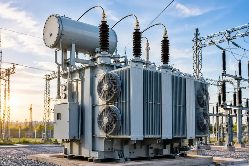
An industrial transformer is a machine that raises or lowers alternating current voltage through electromagnetic induction, so factory equipment receives power at the voltage it was built to run on. It has no moving parts, it does not create energy, and larger units pass on more than 98 percent of the power they receive.
- What it does: changes voltage between two circuits without changing the frequency.
- How it works: AC in the primary winding creates a changing magnetic field in the core, and that field induces voltage in the secondary winding.
- Main types: power, distribution, dry-type, oil-immersed, and isolation transformers.
- Typical lifespan: around 25 to 30 years with sensible loading and regular maintenance.
- Where they are used: factories, steel plants, mines, oil and gas sites, data centers, and renewable energy projects.
Power usually reaches a plant at medium voltage, often 11 kV or 33 kV depending on the country, while motors and control panels run at 400 V or lower. The transformer sits between the two. When it fails, production tends to stop with it, and a replacement can take months to arrive.
This guide goes past the definition. You will see how a transformer works, how each type differs, which protection devices matter, what a good maintenance routine looks like, and how to size and choose a unit for your site. It is written for plant engineers, maintenance teams, and buyers who need practical answers.
What Is an Industrial Transformer?
An industrial transformer is an electrical device that transfers energy between two or more circuits through electromagnetic induction. It changes the voltage level and leaves the frequency unchanged. A small share of the energy is lost as heat, which is why these machines are built with good cooling in mind.
Power travels at high voltage because higher voltage means lower current, and lower current means smaller losses over distance. But a motor on a factory floor cannot run safely on that voltage. The transformer brings it down to a usable level. In other cases it does the opposite, for example at a solar or wind plant where voltage must be stepped up before power enters the grid.
Industrial units differ from the small transformers you might see in electronics or in residential streets. They are designed for higher capacity, long hours of continuous duty, and loads that can be demanding, such as large motors, furnaces, and variable speed drives. You will find them in manufacturing plants, factories, substations, and other heavy industrial systems where stable power is not optional.
How Does an Industrial Transformer Work?
The transformer working principle rests on electromagnetic induction, a discovery credited to Michael Faraday. A basic transformer has three main parts:
- Primary winding: the coil connected to the incoming supply.
- Transformer core: a stack of thin laminated steel sheets that guides the magnetic flux.
- Secondary winding: the coil that delivers power to the load.
When alternating current flows through the primary winding, it creates a magnetic field that rises, falls, and reverses with the current. The core carries that changing field to the secondary winding, where it induces a voltage.
The output voltage depends on the turns ratio, which is the number of turns in the secondary compared with the primary. A secondary with more turns gives a higher voltage, and that is a step-up transformer. A secondary with fewer turns gives a lower voltage, and that is a step-down transformer. Since power stays roughly constant apart from losses, a rise in voltage means a fall in current, and the reverse is also true.
Two details are worth remembering. First, transformers only work with alternating current. Direct current does not produce a changing field, so no voltage is induced. Second, the core is made of laminated sheets, often grain-oriented silicon steel, because a solid block of iron would allow large circulating currents (eddy currents) that waste energy as heat.
Types of Industrial Transformers
Different jobs call for different designs. These are the main types you will meet in industrial settings.
Power Transformers
Power transformers handle high-voltage applications at generating stations and major substations. They are designed to run close to full load for long periods, so designers pay close attention to efficiency at high load. Large industrial substations rely on them to bring transmission voltage down to a level the site can distribute.
Distribution Transformers
Distribution transformers sit closer to the end user. They take medium voltage and step it down to the level your equipment runs on, such as 400 V or 415 V in many regions. Their load changes through the day, so they are built to perform well across a wide range of loading, not only at full capacity.
Dry-Type Transformers
Dry-type transformers use air, not oil, for cooling and insulation. Two common constructions are vacuum pressure impregnated (VPI) and cast resin. They suit indoor installations such as factory buildings, commercial plants, and data centers. With no flammable liquid, the fire risk is lower and there is no oil to leak or test. The trade-off is that they are usually limited to lower voltage and capacity ratings than oil-filled units.
Oil-Immersed Transformers
In an oil-immersed transformer, the core and windings sit in insulating oil that also carries heat away. This design handles high loads well and is widely used outdoors and at large capacities. It needs more attention, including oil quality checks, leak monitoring, and fire safety measures such as barriers or containment pits.
Isolation Transformers
Isolation transformers usually have a one-to-one or similar ratio, and their job is to separate two circuits electrically. They protect sensitive equipment from noise and ground loops, and they add a layer of safety for people working on the equipment. Control panels, laboratory setups, and precision instruments often depend on them.
Special-Purpose Types
Some industries need purpose-built designs. Furnace transformers supply the very high currents needed by arc and induction furnaces. Rectifier transformers feed converters that produce direct current for processes such as electrolysis. Autotransformers share part of one winding between primary and secondary, which makes them compact and economical when the voltage ratio is small.
Many of these types are available as three-phase transformers, which are standard in industrial power systems because they deliver smoother, more efficient power to large motors and loads.
Typical Industrial Transformer Specifications
Exact figures depend on the manufacturer, the country, and the standard followed, but the ranges below give a realistic picture of what industrial buyers deal with.
| Parameter | Typical range or option |
|---|---|
| Primary voltage class | 3.3 kV to 33 kV (higher for large power units) |
| Secondary voltage | 400 V or 415 V common for distribution, other levels for process loads |
| Power rating | A few hundred kVA up to tens of MVA |
| Frequency | 50 Hz or 60 Hz |
| Phases | Three-phase in most industrial sites |
| Cooling | ONAN, ONAF (oil), AN, AF (dry-type) |
| Insulation class (dry-type) | Class F or H commonly used |
| Efficiency | Often above 98 percent at rated load in larger units |
| Expected service life | Around 25 to 30 years with good care |
Cooling codes are easy to decode. ONAN means oil natural, air natural, so heat moves by natural circulation. ONAF adds fans to push air across the radiators for extra capacity. AN and AF are the dry-type equivalents, using natural or forced air.
Distribution Transformer vs Power Transformer
People often mix these two up, and the difference matters when you specify equipment. The short version is that power transformers move bulk energy at high voltage, while distribution transformers deliver it to users at a lower voltage.
| Feature | Distribution Transformer | Power Transformer |
|---|---|---|
| Main application | Electrical distribution | Power transmission and substations |
| Typical location | Near end users | Generating stations and substations |
| Load pattern | Variable through the day | Generally high and continuous |
| Voltage range | Lower | Higher |
| Efficiency focus | All-day distribution efficiency | Efficiency at high, steady load |
The load pattern explains most of the design differences. A distribution transformer rarely runs at full load all day, so keeping no-load losses low is a priority. A power transformer runs near its rating for long hours, so load losses get more attention.
Standards and Testing
A transformer should not be judged on its brochure. It should be judged on the standard it is built to and the tests it passed before leaving the factory. The standards that apply depend on your country and the transformer type, so confirm with your supplier and your local regulations. Commonly referenced ones include:
- IEC 60076 series: the international standard family for power transformers. Part 11 covers dry-type units and Part 10 covers sound level measurement.
- IS 2026 and IS 1180: Indian standards for power and distribution transformers.
- IEEE C57.12 series: widely used in North America for liquid-immersed and dry-type units.
Tests are normally grouped into three kinds:
- Routine tests are done on every unit. They include turns ratio and polarity checks, winding resistance, no-load and load loss measurement, and applied and induced voltage tests.
- Type tests prove the design. A temperature rise test and a lightning impulse test are typical examples, and they are done on a representative unit.
- Special tests are agreed between buyer and manufacturer. Partial discharge, sound level, and short-circuit withstand tests fall here.
When you compare quotations, ask for the test reports. A supplier who can show routine test certificates and the relevant type test reports for the same design is giving you real evidence, not just claims.
Transformer Protection
A transformer is expensive, often has a long lead time, and a failure can stop a whole plant. Protection systems detect abnormal conditions quickly and isolate the unit before a small fault becomes a major one.
Overcurrent Protection
Overcurrent relays and fuses detect current above safe limits, often caused by overloads or downstream faults, and trip the circuit after a set delay. Settings must allow for normal events such as motor starting and the inrush current that flows when a transformer is first energized.
Short-Circuit Protection
Short circuits produce very high currents in a fraction of a second. Circuit breakers and fast-acting relays clear these faults quickly to limit mechanical and thermal damage to the windings.
Overvoltage Protection
Overvoltage can come from switching operations or system disturbances. It stresses the insulation and, over time, shortens the life of the transformer. Overvoltage relays and correctly rated equipment help keep voltage within limits.
Differential Protection
Differential protection compares the current entering the transformer with the current leaving it. If the two do not match as expected, it points to an internal fault such as a winding short, and the relay trips fast. It is common on larger industrial transformers, with the size threshold varying by utility and site practice.
Temperature Protection
Heat is the main enemy of insulation. Winding and oil temperature indicators raise an alarm at one level and trip the transformer at a higher one. In dry-type units, embedded sensors do the same job.
Buchholz Relay Protection
On oil-filled transformers with a conservator tank, the Buchholz relay sits in the pipe between the main tank and the conservator. Slow gas buildup from a minor internal fault triggers an alarm. A sudden surge of oil from a serious fault triggers a trip. It is one of the earliest warning devices for internal problems.
Surge Protection
Lightning and switching surges can puncture insulation. Surge arresters installed near the transformer terminals divert these spikes safely to ground.
Good protection is not about adding every device on the market. It is about matching the scheme to the transformer size, its importance to the process, and the network it connects to.
Industrial Transformer Maintenance
The best maintenance programs are preventive. Instead of waiting for something to fail, you track the condition of the transformer over time and act when trends point the wrong way. Here is what that usually involves.
Visual Inspection
Regular walk-around checks catch many problems early. Look for oil stains, rust, damaged paint, cracked porcelain, loose fittings, unusual noise, and signs of overheating.
Oil Level and Oil Quality Checks
Oil does two jobs, insulation and cooling, so both its level and its condition matter. Routine laboratory tests check moisture content, acidity, and dielectric strength. Dissolved gas analysis can reveal developing faults long before they are visible, which makes it one of the most valuable tools for oil-filled units.
Temperature Monitoring
Compare winding and oil temperatures against the load. A transformer that runs hotter than usual under the same load may have a cooling issue, blocked airflow, or an internal problem.
Insulation Testing
Insulation resistance and polarization index tests show whether insulation is drying out, absorbing moisture, or deteriorating. Trending these results from year to year is more useful than judging a single reading.
Bushing Inspection
Bushings carry current through the tank wall and are a common source of failure. Check for cracks, oil leaks, contamination, and discoloration. Power factor testing can reveal problems you cannot see.
Connection and Terminal Checks
Loose or corroded connections create hot spots. Infrared thermography is a quick, non-intrusive way to find them while the transformer is energized.
Cooling System Inspection
Fans, pumps, radiators, and heat exchangers must work properly. Clean radiators, confirm that fans start at the right temperature, and make sure nothing blocks airflow around dry-type units.
How often to do each task depends on the transformer’s size, age, loading, and environment. Follow the manufacturer’s recommendations and your site standards, and keep every test result in one place so trends are easy to spot.
Common Industrial Transformer Problems
Most transformer issues give some warning before they cause an outage. These are the ones teams run into most often.
Overheating. Typical causes include overloading, poor ventilation, a failing cooling system, harmonics from non-linear loads, or degraded oil. Persistent overheating ages insulation quickly.
Oil leakage. Worn gaskets, loose fittings, corrosion, or damaged bushings are the usual culprits. Even small leaks deserve attention, since low oil reduces cooling and exposes internal parts.
Insulation failure. Moisture, heat, contamination, and age all weaken insulation. Failure often leads to winding faults.
Excessive noise. Some hum is normal. A louder or changed sound can point to loose core laminations, loose mounting, overloading, or overvoltage.
Voltage fluctuations. These may come from a wrong tap setting, supply problems, or heavy load swings. Check the tap changer and the upstream system.
Winding faults. Turn-to-turn shorts or winding-to-ground faults often follow insulation breakdown or damage from a through-fault.
Bushing failure. Moisture ingress and contamination can lead to flashover or violent failure if ignored.
Cooling system problems. Failed fans, clogged radiators, or pump faults let temperature climb, usually under high load when you can least afford it.
Industrial Transformer Applications
Industrial transformers show up wherever large amounts of electrical power are used or generated.
- Manufacturing plants: supplying production lines, motors, welding systems, and process equipment.
- Steel and metal industries: feeding furnaces and rolling mills that draw very high currents.
- Oil and gas facilities: powering pumps, compressors, and process control systems.
- Chemical plants: providing stable power in areas that often need explosion-protected equipment.
- Mining operations: supporting crushers, conveyors, and ventilation in harsh conditions.
- Data centers: delivering clean, reliable power where downtime is extremely costly.
- Industrial automation systems: isolating and stepping down power for control circuits and sensitive electronics.
- Renewable energy facilities: stepping up voltage from solar and wind installations for grid connection.
How to Choose an Industrial Transformer
Selecting the right unit means matching the transformer to the real conditions of your site. These are the factors that matter most.
Voltage requirements. Know the primary supply voltage and the secondary voltage your loads need, plus any tap range required for supply variation.
Load capacity and rating. Transformers are rated in kVA or MVA. For a three-phase load, kVA equals the square root of 3 multiplied by voltage (in volts) and current (in amps), divided by 1000. As a worked example, a 400 V system drawing 800 A needs about 554 kVA. Add a growth margin of around 20 percent and you reach roughly 665 kVA, so the next standard size up, such as 800 kVA, is a sensible choice. Avoid going far beyond this, because an oversized unit wastes energy through no-load losses.
Frequency. Most regions use 50 Hz or 60 Hz. The transformer must match the system frequency.
Installation environment. Consider temperature, altitude, humidity, dust, corrosive air, and available space. High altitude and high ambient temperature can reduce the usable rating.
Indoor or outdoor. Indoor sites often favor dry-type designs. Outdoor sites commonly use oil-filled units with weather-resistant fittings.
Cooling method. Natural cooling suits many applications. Forced air or forced oil cooling supports higher loads in compact spaces.
Dry-type or oil-filled. Dry-type offers lower fire risk and simpler upkeep. Oil-filled offers higher capacity and usually better overload tolerance, but needs more maintenance and fire safety measures.
Harmonics. If your plant has many drives, rectifiers, or UPS systems, tell the supplier. Non-linear loads create extra heating, and a harmonic-rated or K-rated design may be needed.
Efficiency. Look at losses over the whole life of the transformer. A slightly more expensive, more efficient unit often costs less in total.
Protection and maintenance needs. Check that the design supports the protection devices you plan to use, and that your team can realistically maintain it.
Industrial Transformer Efficiency and Energy Losses
Transformers are among the most efficient electrical machines, with large units often above 98 percent. Still, the remaining losses add up over years of continuous operation. They fall into two groups.
Core losses (no-load losses). These occur in the core whenever the transformer is energized, even with no load connected. They come from hysteresis and eddy currents in the steel and stay roughly constant regardless of load.
Copper losses (load losses). These come from the resistance of the windings and rise with the square of the load current. Double the current and these losses roughly quadruple.
Because of this, sizing matters. An oversized transformer running lightly loaded still pays the full core loss. An undersized one runs hot and suffers high copper losses. Maximum efficiency occurs at the load where copper losses equal core losses, and good selection keeps normal operation near that range.
A simple way to see why this matters: a transformer energized 8,760 hours a year pays its core loss every single hour. Over a 25-year life, a lower-loss design can recover its extra purchase cost many times over.
Frequently Asked Questions
What is an industrial transformer?
An industrial transformer is an electrical device used in factories and large facilities to raise or lower voltage through electromagnetic induction, so that equipment receives power at a safe and suitable level.
What are the main types of industrial transformers?
The main types are power transformers, distribution transformers, dry-type transformers, oil-immersed transformers, and isolation transformers. Special designs such as furnace and rectifier transformers serve specific processes.
What is the difference between a power transformer and a distribution transformer?
A power transformer works at higher voltages and usually runs near full load in substations and generating stations. A distribution transformer works at lower voltages, sits near end users, and handles loads that change during the day.
How does an industrial transformer work?
Alternating current in the primary winding creates a changing magnetic field in the core. That field induces a voltage in the secondary winding, and the turns ratio decides whether the voltage rises or falls.
How long does an industrial transformer last?
A well-loaded and well-maintained unit commonly lasts 25 to 30 years, and some last longer. Heavy overloading, poor cooling, and moisture in the insulation shorten that life.
How often should an industrial transformer be maintained?
It depends on size, age, load, and environment. Many sites do frequent visual checks, periodic thermographic and temperature reviews, and oil testing at least once a year for oil-filled units, with deeper electrical tests at longer intervals. Follow the manufacturer’s guidance and your site standards.
What causes an industrial transformer to overheat?
Common causes are overloading, blocked ventilation, cooling system faults, harmonic currents, poor connections, and degraded insulating oil. Finding the cause early prevents long-term insulation damage.
What protection is required for an industrial transformer?
Requirements depend on size and importance, but typical protection includes overcurrent, short-circuit, temperature, and surge protection. Larger units often add differential protection, and oil-filled units with conservators commonly use a Buchholz relay.
Conclusion
Industrial transformers are a small part of the electrical system on paper, but they carry a large share of the responsibility for keeping a plant running. Knowing how they work, understanding the difference between types, and choosing a design that fits your load and environment gives you a strong start. Protection devices guard against sudden faults, and a steady preventive maintenance routine catches slow problems before they become outages.
If you are planning a new installation or reviewing an existing one, begin with your real load profile and site conditions. Then work through protection, maintenance, and efficiency together. Decisions made at that stage tend to pay off for decades.
You May Also Like It:
Bonding vs Grounding: What’s the Difference?
Industrial Electrical System: A Complete Guide to Components, Installation, and Maintenance
Industrial Switchgear: Types, Design, and How to Choose the Right Syste
Author: Midwest Industries Editorial Team
Reviewed by: Midwest Industries Editorial Team
Last updated: October 1, 2026